Special-shape vacuum suction disc sucking and lifting device and method

A technology of vacuum suction cups and vacuum slings, applied in the direction of load hanging components, transportation and packaging, etc., can solve the problems of increasing the success rate of operation and positioning, shortening the operation and positioning time, and being easy to be pulled off, so as to reduce personnel operations and protect Safety, impact reduction effect

Inactive Publication Date: 2012-11-14
上海优乐博特自动化工程有限公司
View PDF8 Cites 6 Cited by
  • Summary
  • Abstract
  • Description
  • Claims
  • Application Information

AI Technical Summary

Problems solved by technology

[0007] The task of the present invention is to provide a special-shaped corner material vacuum suction cup sling and suction lifting method, which solves various problems in production, improves the service life of the sling, and eliminates the serious wear and tear of the suction cup rubber during the suction cup adsorption process. To solve the problem of being pulled off, a new centering guide mechanism was introduced, which added the self-detection function of the horizontal placement of the spreader and the self-compensation function of the lateral adjustment error of the suction cup, which shortened the operation positioning time, increased the success rate of operation positioning, and reduced the The number of production interruptions due to the spreader, which improves the production efficiency of special-shaped angle materials (hollow square piles)

Method used


Image

  • Special-shape vacuum suction disc sucking and lifting device and method
  • Special-shape vacuum suction disc sucking and lifting device and method
  • Special-shape vacuum suction disc sucking and lifting device and method

Examples


Embodiment Construction

[0042] The present invention will be described in detail below in conjunction with the accompanying drawings and embodiments.

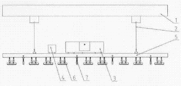
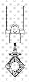
[0043] see Figure 1 to Figure 7 , The special-shaped corner material vacuum suction cup spreader of the present invention is mainly composed of a lifting crane 1, a wire rope hook 2, a vacuum pump and a control system 3, an electrical control box 4, a main beam of the vacuum spreader 5, a vacuum suction cup set 6 and a centering guide mechanism 7 composition. The vacuum suction cup group 6 is installed on the main beam 5 of the vacuum lifter. At least two sets of centering guide mechanisms 7 are installed on the main beam 5 of the vacuum lifter.

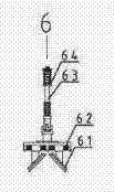
[0044] The vacuum chuck group 6 comprises two vacuum chucks 61, a lateral adjustment spring 62, a vertical guide shaft 63, and a vertical adjustment spring 64. The horizontal adjustment spring 62 is arranged between the two vacuum chucks 61 to adjust the lateral displacement between them, and the vertical...


PUM


Abstract

The invention relates to a special-shape vacuum suction disc sucking and lifting device and method. A vacuum suction disc group and at least two groups of centering guiding mechanisms are arranged on the main beam of the vacuum lifting device; a transverse adjustment spring is arranged between two vacuum suction discs in the vacuum suction disc group so as to adjust the mutual transverse displacement of the vacuum suction discs; each centering guidng mechanism is provided with more than four rolling wheels; the rolling wheels are arranged on a reversed V-shaped support leg; a guiding sleeve is arranged on the upper part of the reversed V-shaped support leg; a spring which guiding downwards is supported and arranged in the guiding sleeve; the top of the guiding sleeve is provided with a guiding shaft; a downward displacement adjustment rod is hung in the upper component of the guiding sleeve. One or more groups of vacuum suction discs are distributed in the length direction of a special-shape angel section, a crane trolley is started, the vacuum suction disc group is make to descend to cling to the special-shape angel section through a steel wire rope to form a sealed vacuum cavity, and the special-shape angel section is lifted. Due to the adoption of the special-shape vacuum suction disc sucking and lifting device, the production efficiency is improved, the security is improved, and the influence of the human factors to the product quality is reduced.

Description

technical field [0001] The invention relates to a vacuum sling, in particular to a vacuum suction cup sling and a suction lifting method for handling special-shaped corner materials. The so-called special-shaped angle material refers specifically to special-shaped pipes, special-shaped piles and other profiles whose cross-sectional shape involves equilateral right angles, especially hollow square piles, solid square piles, special-shaped steel pipes, angle steel and other profiles. Background technique [0002] Vacuum spreaders have been widely used in developed countries as early as the middle of the last century. Our country's understanding of vacuum spreaders began at the end of the last century and has been continuously developed at the beginning of this century. At present, vacuum lifters have been used in all walks of life in China. Industry. Aiming at a vacuum handling spreader for special-shaped angle materials and absorbing two right-angled surfaces involved in the...

Claims


Application Information

Patent Timeline
Patent Type & Authority Applications(China)
IPC IPC(8): B66C1/02
Inventor 周旭明王彬
Owner 上海优乐博特自动化工程有限公司
Why Eureka
Try Eureka