Eureka AIR delivers breakthrough ideas for toughest innovation challenges, trusted by R&D personnel around the world.

Carbon fiber yarn fiber-stretching mechanism

A carbon fiber and yarn technology, used in textiles and papermaking, knitting, warp knitting and other directions, can solve the problems of bound carbon fiber yarn application, poor laying performance, and the quality of subsequent parts cannot be well guaranteed.

Active Publication Date: 2012-11-14
CHANGZHOU HONGFA ZONGHENG ADVANCED MATERIAL TECH
View PDF13 Cites 10 Cited by
  • Summary
  • Abstract
  • Description
  • Claims
  • Application Information

AI Technical Summary

Problems solved by technology

However, the fabric produced by 12K carbon fiber yarn on the market currently has the smallest single-layer unit area mass of 190g / m 2 , while the density of carbon fiber yarn is only 1.8g / m 3 , so this kind of fabric is relatively thick, with large deviations in mechanical properties, especially the poor covering performance, so that the quality of the subsequent parts cannot be well guaranteed, which seriously restricts the use of carbon fiber yarns in the high-end field. Applications

Method used


Image

  • Carbon fiber yarn fiber-stretching mechanism
  • Carbon fiber yarn fiber-stretching mechanism
  • Carbon fiber yarn fiber-stretching mechanism

Examples


Embodiment Construction

[0034] The present invention will be further described in detail below in conjunction with the accompanying drawings and specific embodiments.

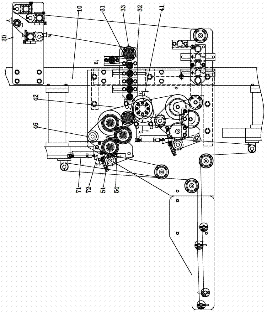
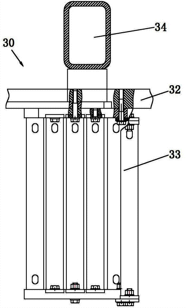
[0035] refer to Figure 1 to Figure 6 , the carbon fiber yarn spreading mechanism in the present invention includes a support 10, a wire device 20, a heating spreading device 30, a synchronous driving device 40, a roller spreading device 50, a tension balance spreading device 60 and a thrust device, respectively below The structure of each part is explained in detail:

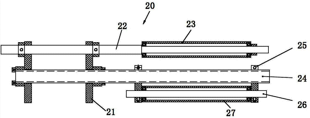
[0036] refer to figure 1 and figure 2 , the wire guide device 20 is fixed on the upper part of the bracket 10, and the wire guide device guides the input carbon fiber yarn and exerts a pulling force. The guide wire device includes a mounting plate 21 , an intermediate roller shaft 22 , a first guide roller 23 , a yarn passing shaft 24 , a splint 25 , a shaft 26 and a second guide roller 27 . Mounting plate 21 is used to be fixed on the support 10, and one end of t...


PUM

PropertyMeasurementUnit
densityaaaaaaaaaa

Abstract

The invention relates to a carbon fiber yearn fiber-stretching mechanism. A yarn guide device is fixed on the upper part of a bracket; the guide device guide input carbon fiber yarns and applies tensile force to act the carbon fiber yarns; a heating and fiber-stretching device is fixed on the bracket and arranged on the downstream of the yarn guide device; the heating and fiber-stretching device heats up the passed carbon fiber yarns, so that the carbon fiber yarns are stretched; a synchronous drive device is fixed on the middle part of the bracket; the synchronous drive device drives a roller fiber-stretching device to rotate so as to drive the carbon fiber yarns to continuously move; the roller fiber stretching device is fixed on the bracket and arranged on the downstream of the heating and fiber stretching device; and the roller fiber stretching device re-stretches the carbon fiber yarns which are stretched by the heating and fiber stretching device.

Description

technical field [0001] The invention relates to a carbon fiber yarn spreading mechanism. Background technique [0002] Carbon fiber multi-axial warp knitted fabric preforms / LCM process parts have been successfully applied on the new generation of large aircraft Airbus A380, Boeing 787 and Airbus A400M; the rear of Airbus A380 and Boeing 787 aircraft The dome-shaped frame shell of the pressure frame is preformed with 0° / 90° warp-knitted carbon fiber fabric; A380 outer wing spar; A400M cargo door; A380 window frame is made of carbon fiber multiaxial warp-knitted fabric sewing reinforcement ribs. At present, my country has successively built a number of large-scale projects; large aircraft, large-scale offshore wind power generation, lightweight automobile tracks, etc., all require a large amount of carbon fiber multi-axial warp knitted fabrics. This product has a very broad application prospect in our country. [0003] Tests on carbon fiber fabrics have shown that the thinne...

Claims


Application Information

Patent Timeline
Patent Type & Authority Applications(China)
IPC IPC(8): D02J1/18D04B27/00D04B27/02D04B35/26
Inventor 谈昆伦钱亚刚陈龙谈良春
Owner CHANGZHOU HONGFA ZONGHENG ADVANCED MATERIAL TECH
Why Eureka
Eureka Blog
Learn More