Method for fast predicting side wall leakage of underground diaphragm wall using infrared thermal fields

A technology of underground diaphragm wall and thermal field, which is applied in the test of foundation structure, construction, foundation structure engineering, etc., and can solve the problems of underground diaphragm wall leakage and failure to take into account

Inactive Publication Date: 2012-11-14
TONGJI UNIV
View PDF4 Cites 17 Cited by
  • Summary
  • Abstract
  • Description
  • Claims
  • Application Information

AI Technical Summary

Problems solved by technology

However, these patents have not considered the use of thermal imaging cameras, thermal field images and thermal field analysis to judge the leakage of underground diaphragm walls

Method used


Image

  • Method for fast predicting side wall leakage of underground diaphragm wall using infrared thermal fields
  • Method for fast predicting side wall leakage of underground diaphragm wall using infrared thermal fields
  • Method for fast predicting side wall leakage of underground diaphragm wall using infrared thermal fields

Examples


Embodiment 1

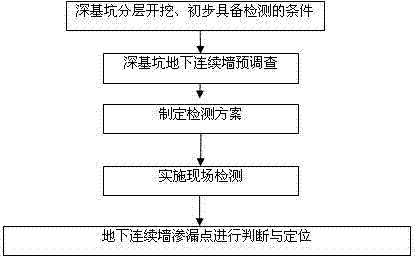
[0026] Embodiment 1: Taking the leakage point test of the underground diaphragm wall of a foundation pit in a certain area as an example, the specific application is carried out according to the following steps:

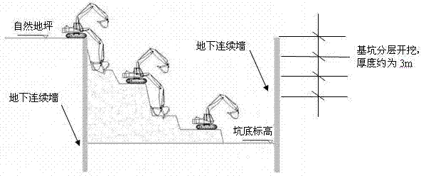
[0027] Project overview: On-site geological survey shows that within the influence range of the underground diaphragm wall of the target foundation pit, the stratum is divided into 3 layers, and the depth of the foundation pit is 9m. 1 A layer of silty clay with a thickness of 1.5m;② 3 A layer of sandy silt with a thickness of 3.6m; ③ a layer of muddy silty clay with a thickness of 2.4m; layer ④ is a layer of medium-sand and other soils with better stress.

[0028] Step 1: The deep foundation pit is excavated in layers. According to the requirements of the design drawings and construction specifications, after the water is pumped down to 0.5 m below the bottom of the foundation pit, the deep foundation pit can be excavated in layers, with a layer thickness of 3m.

...


PUM


Abstract

The invention relates to a method for fast predicting side wall leakage of an underground diaphragm wall using infrared thermal fields. The method includes: performing layered excavation to a deep foundation pit; pre-investigating the underground diaphragm wall of the deep foundation pit, and paying attention to positions such as voids and pits, cavities, water seepage surfaces and water gushing surfaces to further determine detecting range and objects; detailing detection time, targets and methods according to pre-investigating results to form a formal detection scheme; using an infrared thermal imager to detect the targets to form images according to the detection scheme and recording and saving the related thermal field images; judging leakage points of the underground diaphragm wall; and analyzing and judging abnormal thermal fields so as to judge and position the leakage points. The method uses clear principles, and is highly adaptive and economical. The infrared thermal imager is used to detect the infrared thermal fields so as to judge and position the leakage points of the underground diaphragm wall of the foundation pit while construction of the foundation pit is not affected. Accordingly, fast and convenient judging and positioning of the leakage of the underground diaphragm wall of the foundation pit are achieved.

Description

technical field [0001] The invention belongs to the field of leakage detection of the side wall of the underground diaphragm wall mainly used in municipal engineering, industrial and civil construction projects, and specifically relates to a method for quickly predicting the side wall leakage of the underground diaphragm wall by using an infrared heat field. Background technique [0002] In the construction of foundation pits, especially in the excavation construction of super-large and super-deep foundation pits, the underground diaphragm wall plays an important role in ensuring safety. If the underground diaphragm wall leaks, the sideways of the foundation pit will easily collapse, causing adverse effects on the construction in the foundation pit, and in serious cases, it will threaten the construction or even directly cause a major foundation pit safety accident. Therefore, leakage monitoring is an important link in the construction of underground diaphragm walls in found...

Claims


Application Information

Patent Timeline
Patent Type & Authority Applications(China)
IPC IPC(8): E02D33/00
Inventor 王建秀黄天荣邹宝平
Owner TONGJI UNIV
Why Eureka
Try Eureka