A construction method for unloading U-shaped trough of high-rise buildings

A high-rise building and construction method technology, applied in the processing of building materials, construction, building construction, etc., can solve the problems that construction elevators are difficult to meet the material transportation requirements, the loading capacity of bucket trucks is limited, and affect the civilized construction of projects, etc., to ensure that The effects of safe and civilized construction, saving purchase costs, and convenient installation and disassembly

Active Publication Date: 2014-10-15
THE THIRD CONSTR & ENG OF CCFED
View PDF5 Cites 0 Cited by
  • Summary
  • Abstract
  • Description
  • Claims
  • Application Information

AI Technical Summary

Problems solved by technology

Generally, the material transportation of high-rise buildings mainly depends on human-powered bucket trucks to be transported vertically to the construction elevator. The disadvantages of this transportation method are: (1) Due to the limited loading capacity of bucket trucks, it requires a lot of labor
(2) During the construction of high-rise building decoration projects, due to the increasingly tight construction period, various decorative materials need to be transported to the construction floor, and construction elevators are difficult to meet the material transportation requirements
(4) Due to the tight capacity of the construction elevators, it is inevitable that the mortar transportation needs to wait in line, which may easily cause the quality of the mortar to decline
(5) Mortar is easily splashed on the ground during transportation by bucket truck, which affects the civilized construction of the project

Method used


Image

  • A construction method for unloading U-shaped trough of high-rise buildings
  • A construction method for unloading U-shaped trough of high-rise buildings

Examples


Embodiment Construction

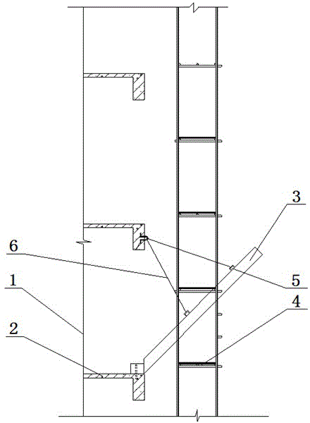
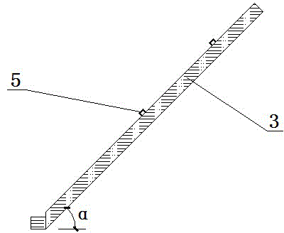
[0015] Embodiments of the present invention: as figure 1 As shown, first install the platform cantilevered on the outer edge of the building that matches the height of the floor, and install a sliding unloading plate inclined to it on the platform of the working layer (the working layer is the first floor of unloading construction), and slide unloading The boards are not in contact with the outer scaffolding. After the installation is completed, the construction personnel stand on the external scaffolding and operate the tower crane to unload the material onto the sliding unloading plate, and the material can slide into the building under the action of gravity to complete the unloading. After the construction of the working layer is completed, it will be lifted layer by layer, and the sliding unloading plate will be installed to carry out the unloading construction until the unloading construction of all floors of the entire building is completed. In order to save constructio...


PUM


Abstract

The invention discloses a U-shaped slot unloading construction method for high buildings. The method comprises the following steps that: a platform is installed on a cantilever of the outer edge of a building matched with the floor height, and a sliding unloading plate which inclines towards the platform is installed on the platform of an operation level without contacting an outer scaffold; after the installing is finished, a constructor stands on the outer scaffold, operates a cableway bucket of a tower crane to unload on the sliding unloading plate, in this way, the material can slide downwards in the building so as to finish the unloading; lifting floor by floor is carried out after the construction of the operation level is finished, the sliding unloading plate is installed, and the unloading construction is performed till the unloading construction of all floors of the whole building are finished. Practices prove that, with the adoption of the U-shaped slot, a large amount of manpower and a large amount of trolley cost are saved; the construction method has the following characteristics of convenience, high speed, good economic benefit, reduced manpower, and ensured safe and civilized construction; and the construction is especially suitable for high buildings, ultra-high buildings, and multi-floor buildings with complex decoration engineering.

Description

technical field [0001] The invention relates to the field of building construction, in particular to a construction method for unloading U-shaped grooves of high-rise buildings. Background technique [0002] In the construction of high-rise building decoration projects, the transportation volume of decorative materials such as mortar is huge, and how to ensure the safe and convenient transportation of materials has always been a difficult problem. Generally, the material transportation of high-rise buildings mainly relies on human-powered bucket trucks to transport vertically to the construction elevator. The disadvantages of this transportation method are: (1) Due to the limited loading capacity of bucket trucks, it requires a lot of labor. (2) During the construction of high-rise building decoration projects, due to the increasingly tight project schedule, various decorative materials need to be transported to the construction floor, and construction elevators are difficul...

Claims


Application Information

Patent Timeline
Patent Type & Authority Patents(China)
IPC IPC(8): E04G21/14E04G21/16
Inventor 杨广海钟佳
Owner THE THIRD CONSTR & ENG OF CCFED
Why Eureka
Try Eureka