
Installation technology of inner separation wall body

An installation process and wall technology, applied in the direction of walls, building materials, building components, etc., can solve the problems of inconvenient operation, labor and time-consuming, inconvenient to ensure the verticality and flatness of the board, and achieve easy installation, Easy to operate, guarantee the effect of flatness and verticality

Inactive Publication Date: 2012-11-14
中山建华墙体材料有限公司
View PDF5 Cites 22 Cited by
  • Summary
  • Abstract
  • Description
  • Claims
  • Application Information

AI Technical Summary

Problems solved by technology

The installation process of the existing inner partition wall has the following disadvantages: 1. The verticality of a whole wall and the ground and the structural wall column mainly depends on the verticality of the first wallboard. When installing the first wall panel, workers need to check the positions of the antenna line and the ground line, and after repeated adjustments to the position of the wall panel to ensure the flatness and verticality of the wall panel, the operation is very inconvenient and labor-intensive. time consuming
2. The connection between wall panels and beam panels needs to be reinforced with steel bars, which is very inconvenient to operate, labor-intensive and time-consuming
3. When the wall panel and the structural wall are installed at a 90-degree corner, the steel bars need to be driven in after installation, which is not easy to ensure the verticality and flatness of the panel, and the operation is very inconvenient

Method used


Image

  • Installation technology of inner separation wall body
  • Installation technology of inner separation wall body
  • Installation technology of inner separation wall body

Examples


Embodiment Construction

[0045] The present invention will be further described below in conjunction with accompanying drawing description and specific embodiment:

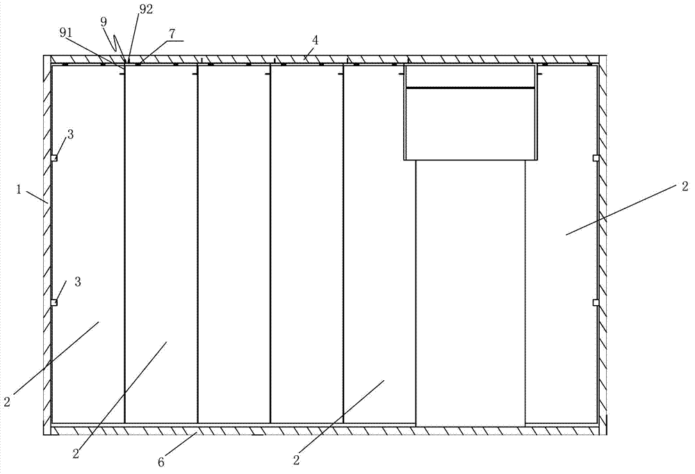
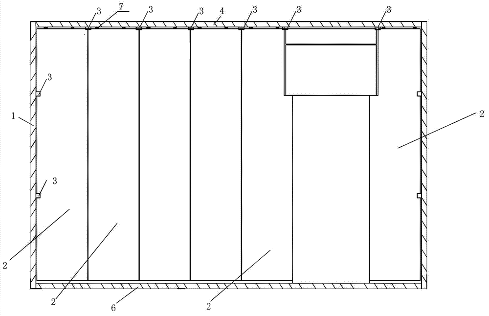
[0046] Such as Figures 1 to 13 Shown, the present invention is a kind of installation process of inner partition wall body, and it comprises the following steps:

[0047] A. Positioning and setting out: release the wall line on the construction site to position the inner partition wall to be installed. The wall line includes the ground line and the antenna line;

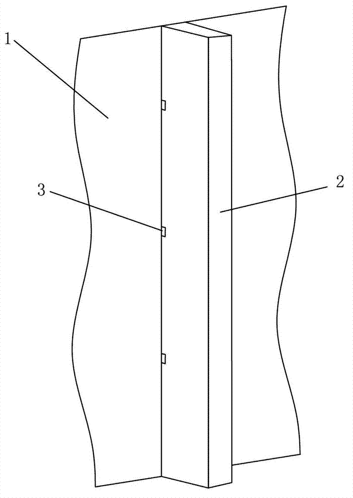
[0048] B. Install the U-shaped positioning clip 3: the U-shaped positioning clip 3 includes a connecting piece 31,

[0049] The first card 32 and the second card 33 perpendicular to it are respectively connected to both sides of the connecting piece 31, and the inner surface of the connecting piece 31 is formed between the first card 32 and the second card 33 for placing the wallboard 2. The mounting groove 34, the width of the mounting groove 34 is equivalent to the thicknes...


PUM


Abstract

The invention discloses an installation technology of an inner separation wall body. The installation technology comprises the following steps of: locating and despooling; installing U-shaped locating clamping pieces; continuously installing wallboards; and taking out wedge blocks: wherein when the U-shaped locating clamping pieces are installed, at least more than two U-shaped locating clamping pieces are installed on a structural wall column along a vertical direction, installing grooves of all the U-shaped locating clamping pieces are arranged in a row on the vertical direction, multiple interval wedge blocks, of which the top surfaces can be pressed tightly to a beam board, are knocked between the bottom surface of a first wall board and a floor board, and multiple gaps formed between the floor board and the wall board are respectively filled with mortars. By adopting the installation technology disclosed by the invention, multiple U-shaped locating clamping pieces can be arranged in a row in the vertical direction and can be fixedly arranged on the surface of the structural wall column when the first wall board of a wall body is installed, the first wall board can be then located by the U-shaped locating clamping pieces, the first wall board can be quickly located, the time and the labor are saved, and the flatness and the verticality of the wall boards are ensured.

Description

technical field [0001] The invention relates to an installation process of an inner partition wall. Background technique [0002] For the installation of the existing inner partition wall, generally the first wallboard is connected on the structural wall column with mortar, and then the wallboards are installed in sequence to complete the installation of the whole body of wall. The installation process of the existing inner partition wall has the following disadvantages: 1. The verticality of a whole wall and the ground and the structural wall column mainly depends on the verticality of the first wallboard. When installing the first wall panel, workers need to check the positions of the antenna line and the ground line, and after repeated adjustments to the position of the wall panel to ensure the flatness and verticality of the wall panel, the operation is very inconvenient and labor-intensive. time consuming. 2. The connection between the wall board and the beam board ne...

Claims


Application Information

Patent Timeline
Patent Type & Authority Applications(China)
IPC IPC(8): E04G21/14E04B2/82
Inventor 许景新周传翠黄绍有宋震峰
Owner 中山建华墙体材料有限公司
Learn More