Air supply device and air-conditioning indoor unit

A technology of air supply device and cavity, which is applied to pump devices, parts of pumping devices for elastic fluids, mechanical equipment, etc., which can solve the problems of difficulty in meeting comfort control standards, ineffective use of space, and air supply problems. Short distance and other issues, to achieve the effect of simple structure, lower production cost and maintenance cost, and long air supply distance

Active Publication Date: 2012-11-14
MIDEA GRP CO LTD
View PDF8 Cites 15 Cited by
  • Summary
  • Abstract
  • Description
  • Claims
  • Application Information

AI Technical Summary

Problems solved by technology

The reason is that due to the characteristics of their respective internal structures, it is difficult to reduce the diameter of the air-conditioning indoor unit using a centrifugal fan system to an ideal size, and it is difficult to expand its diameter to an ideal size for an air-conditioning indoor unit using a cross-flow fan system. size of
As a result, the indoor unit of the air conditioner had to adopt a rectangular structure design, resulting in a large amount of space inside it not being effectively utilized
[0003] In addition, there is an air-conditioning indoor unit with an axial-flow air duct or an inclined-flow air duct that can be designed in a cylindrical structure, which can solve the above-mentioned technical problems, but this kind of air-conditioning indoor unit has the characteristics of large noise, short air supply distance, and difficulty in achieving relevant comfort. Disadvantages such as sexual control standards

Method used


Image

  • Air supply device and air-conditioning indoor unit
  • Air supply device and air-conditioning indoor unit
  • Air supply device and air-conditioning indoor unit

Examples


Embodiment Construction

[0033] The technical solutions of the present invention will be further described below in conjunction with the accompanying drawings and specific embodiments. It should be understood that the specific embodiments described here are only used to explain the present invention, not to limit the present invention.

[0034] The invention provides an air supply device.

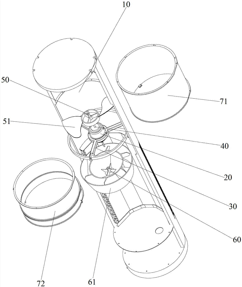
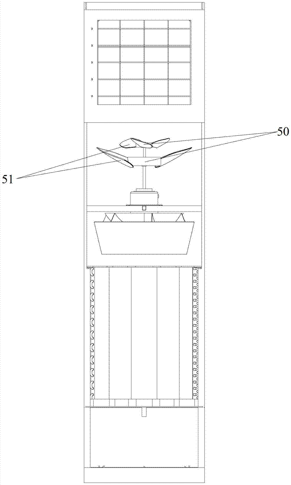
[0035] refer to figure 1 and figure 2 , figure 1 It is a schematic diagram of the assembly structure of an embodiment of the air supply device of the present invention; figure 2 It is a schematic diagram of the explosive structure of an embodiment of the air supply device of the present invention.

[0036] In this embodiment, the air supply device includes a housing 10, a motor 20, a motor bracket 30, a motor shaft 40, an axial flow wind wheel 50, a diagonal flow wind wheel 60 and a volute, wherein the housing 10 has an opening at both ends The cylindrical cavity has two open ends for air inlet and outlet re...


PUM


Abstract

The invention discloses an air supply device which comprises a shell, a motor, an oblique flow wind wheel, at least one axial flow wind wheel and a volute, wherein the shell is provided with a cylindrical cavity of which two ends are open; the motor is accommodated in the cylindrical cavity of the shell and is fixed through a motor bracket; the oblique flow wind wheel is arranged at one end of a motor shaft of the motor; the at least one axial flow wind wheel is arranged at the other end of the motor shaft; oblique flow fan blades are arranged on the oblique flow wind wheel; axial flow fan blades are arranged on the axial flow wind wheel; the volute is arranged corresponding to the axial flow wind wheel and the oblique flow wind wheel and is fixed on the inner wall of the shell; the motor bracket is fixed on the inner wall of the shell or the inner wall of the volute; and an air duct is formed by the axial flow fan blades, the oblique flow fan blades and the volute. The inner space of the shell can be effectively used; and meanwhile, the noise is easily reduced to a standard range under the condition that the air quantity is guaranteed, and the air supply distance is farther. The invention also discloses an air-conditioning indoor unit.

Description

technical field [0001] The invention relates to the technical field of air conditioners, in particular to an air supply device and an air conditioner indoor unit. Background technique [0002] Existing split-floor air-conditioning indoor units usually use a centrifugal fan system or a cross-flow fan system. Regardless of whether a centrifugal fan system or a cross-flow fan system is used, the overall shape generally adopts a rectangular structure design, and It is not a design with a cylindrical structure with higher space utilization. The reason is that due to the characteristics of their respective internal structures, it is difficult to reduce the diameter of the air-conditioning indoor unit using a centrifugal fan system to an ideal size, and it is difficult to expand its diameter to an ideal size for an air-conditioning indoor unit using a cross-flow fan system. size of. As a result, the air-conditioning indoor unit has to adopt a rectangular structure design, resulti...

Claims


Application Information

Patent Timeline
Patent Type & Authority Applications(China)
IPC IPC(8): F04D25/16F04D29/40F04D29/66
Inventor 张惟黎文斗游斌周拨刘阳黄剑云周何杰
Owner MIDEA GRP CO LTD
Why Eureka
Try Eureka