Pipeline freezing rust scale layer structure sampling method

A layered structure and pipeline technology, applied in the field of sampling, can solve the problems of unable to guarantee the quality of sampling, destroy the layered structure of pipeline rust and scale, etc., and achieve the effect of convenient operation, high feasibility and large air volume

Active Publication Date: 2012-10-03
哈尔滨凯纳科技股份有限公司
View PDF4 Cites 4 Cited by
  • Summary
  • Abstract
  • Description
  • Claims
  • Application Information

AI Technical Summary

Problems solved by technology

[0004] The purpose of the present invention is to provide a method for sampling the layered structure of frozen rust in pipelines, so as to solve the problem that the original rust layered structure of the pipeline is destroyed when sampling with traditional scalers, and the quality of sampling cannot be guaranteed.

Method used


Image

  • Pipeline freezing rust scale layer structure sampling method
  • Pipeline freezing rust scale layer structure sampling method

Examples


specific Embodiment approach 1

[0016] Specific implementation mode one: combine figure 1 and figure 2 Describe this implementation mode, this implementation mode comprises the following steps:

[0017] Step 1: Sampling point positioning process:

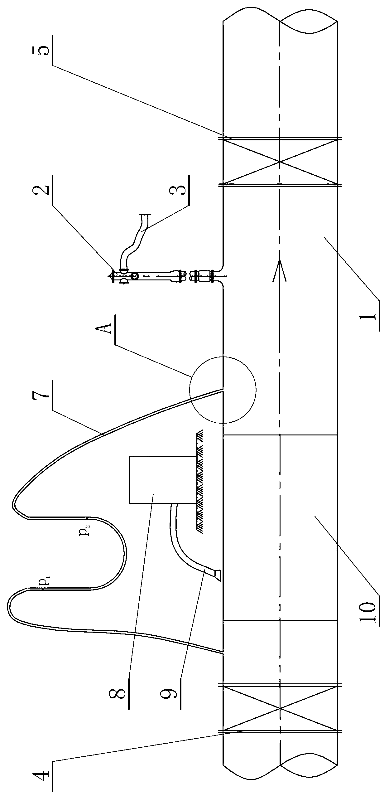
[0018] First select the stable water supply pipeline 1 as the sampling object, arbitrarily select a fire hydrant 2 on the stable water supply pipeline 1 as the sampling reference point;

[0019] Step 2: Auxiliary equipment installation and positioning process:

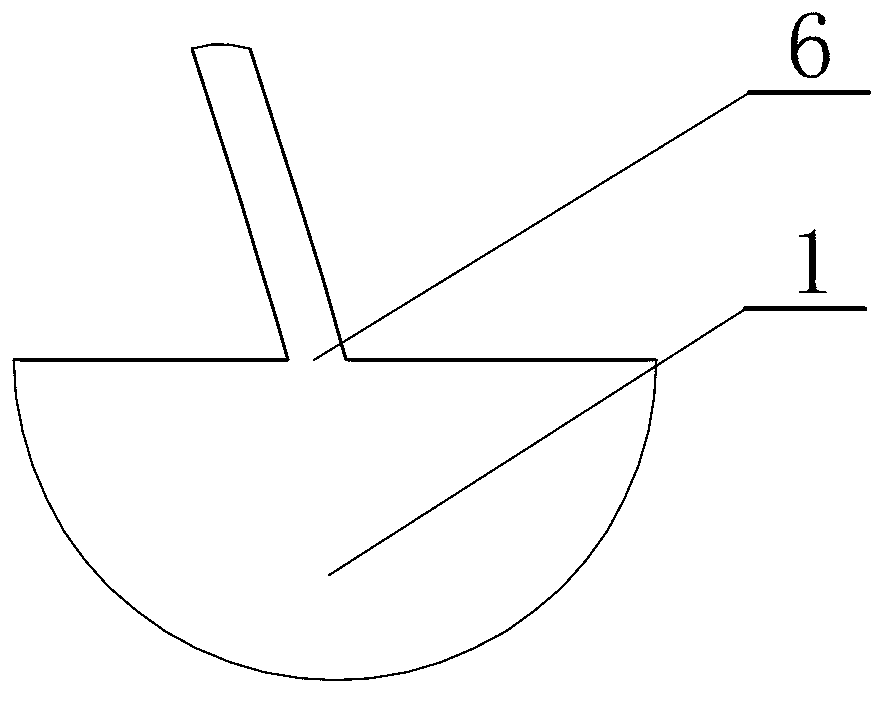
[0020] After the sampling point positioning process is completed, firstly, the fire hydrant 2 is fixedly connected with a drain hose 3, and then an upstream valve 4 and a downstream valve 5 are respectively installed at the front and rear ends of the water supply pipeline 1 where the fire hydrant 2 is located, and then Two through holes 6 are processed on the water supply pipe 1 between the fire hydrant 2 and the upstream valve 4, and the two ends of the U-shaped rubber hose 7 pass through the two thro...

specific Embodiment approach 2

[0025] Specific implementation mode two: combination figure 1 and figure 2 To describe this embodiment, the length of the sampling pipe 10 in this embodiment is 0.3-0.8 m. Other methods and steps are the same as those in the first embodiment.

specific Embodiment approach 3

[0026] Specific implementation mode three: combination figure 1 and figure 2 Describe this implementation mode, step 1 of this implementation mode: sampling point positioning process:

[0027] First select the stable water supply pipeline 1 as the sampling object, arbitrarily select a fire hydrant 2 on the stable water supply pipeline 1 as the sampling reference point;

[0028] Step 2: Auxiliary equipment installation and positioning process:

[0029] After the sampling point positioning process is completed, firstly, the fire hydrant 2 is fixedly connected with a drain hose 3, and then an upstream valve 4 and a downstream valve 5 are respectively installed at the front and rear ends of the water supply pipeline 1 where the fire hydrant 2 is located, and then Two through holes 6 are processed on the water supply pipe 1 between the fire hydrant 2 and the upstream valve 4, and the two ends of the U-shaped rubber hose 7 pass through the two through holes 6 to communicate with ...


PUM

PropertyMeasurementUnit
lengthaaaaaaaaaa

Abstract

The invention discloses a pipeline freezing rust scale layer structure sampling method, relating to a sampling method. The invention aims at solving the problems that the traditional rust scale device damages the original rust scale layer structure of the pipeline during sampling and the sampling quality can not be ensured. The pipeline freezing rust scale layer structure sampling method comprises the steps of: positioning a sampling point, to be specific, freely selecting a fire hydrant on a water supply pipeline with stable water supply as a sampling reference point; installing and positioning an auxiliary device, to be specific, installing an upstream valve, a downstream valve and a U-shaped rubber hose and processing two through holes; freezing, to be specific, freezing a water supply pipeline through an industrial air cooler; and sampling, to be specific, sampling the water supply pipeline reaching the freezing requirement through an electric saw. The pipeline freezing rust scale layer structure sampling method is simple in operation, and brings the convenience for experiment observation of the rust scale layer structure in the sampled pipeline. The pipeline freezing rust scale layer structure sampling method is used for sampling the water supply pipeline.

Description

technical field [0001] The invention relates to a sampling method, in particular to a sampling method for the layered structure of frozen rust scale in pipelines. Background technique [0002] The water supply pipeline will form rust and scale during long-term operation. Rust scale refers to the combination of yellowish brown, porous and uneven layer of sediment, rust and sticky scale on the inner wall of the pipe; the rust scale is from the inside to the The outer layers are corrosion layer, post-sedimentation layer, and biofilm layer. The existence of biofilm on the water supply pipeline will cause problems such as water quality, including the growth of pathogenic bacteria, the increase of chroma and turbidity, the intensification of pipeline corrosion, the shrinkage of water cross section, the occurrence of pipe burst, the increase of energy consumption, the Reduced water capacity, etc., pose a threat to the safety of drinking water. Analyzing the layered structure of p...

Claims


Application Information

Patent Timeline
Patent Type & Authority Applications(China)
IPC IPC(8): G01N1/04G01N1/42
Inventor 高金良庄永伟李月朋
Owner 哈尔滨凯纳科技股份有限公司
Why Eureka
Try Eureka