Sleeve clip type measurement tripod
A technology for measuring feet and collets, which is applied to measuring devices, measuring instruments, surveying and navigation, etc. It can solve the problems of reducing measurement accuracy, increasing measurement difficulty, and reducing measurement accuracy, so as to achieve easy operation and improve measurement efficiency and the effect of precision
- Summary
- Abstract
- Description
- Claims
- Application Information
AI Technical Summary
Problems solved by technology
Method used
Image
Examples
Embodiment 1
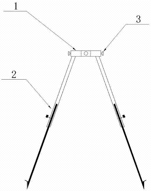
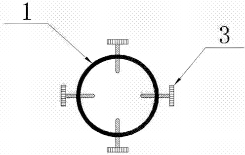
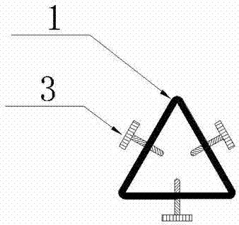
[0015] Such as figure 1 , 2 , Shown in 3 and 4: same as the prior art, there is a base 1 arranged horizontally and a foot 2 connected with the base 1, what is different from the prior art is that the base 1 is annular, and in the annular At least three horizontal jacking wires 3 are evenly distributed on the base 1 , that is, the horizontal jacking wires 3 are located on the horizontal plane of the annular base 1 . The ring-shaped base 1 can be a closed integrated structure, or an open and closed split structure, and can be in various shapes at the same time, such as figure 2 It is shown as a circle, and four top wires 3 are evenly distributed on the circumference, such as image 3 Shown as a triangle, a top wire 3 is set on each side of the triangle, as Figure 4 Shown is a quadrilateral with a top wire 3 provided on each side of the quadrilateral.
[0016] Using Embodiment 1 of the present invention as Figure 5 As shown: the leveling rod, total station reflective pris...
Embodiment 2
[0018] Such as Figure 6 Shown: the basic structure is the same as that of embodiment 1, and the difference from embodiment 1 is that there is an instrument support rod 4 built into the annular base 1, and an instrument mounting seat 5 is connected to the end of the instrument support rod 4, and the side of the instrument support rod 4 is marked with Altitude scale6. The instrument mount 5 is the same as the existing tripod, and is made of plate bases and fixings such as screws.
[0019] Place the instrument support rod 4 on the measurement mark point, adjust the flare angle and length of the foot 2, make the instrument support rod 4 stable and roughly vertical, and fix the measuring instruments such as theodolite, level and total station on the instrument mounting base 5 , Fine-tune the top wire 3 to accurately level the measuring instrument. Through the height scale 6 on the side of the instrument support rod 4, the vertical distance between the instrument observation refe...
Embodiment 3
[0021] Such as Figure 7 , Figure 8 Shown: the basic structure is the same as that of Embodiment 1, and the difference from Embodiment 1 is that the first shaft 7 is flexibly connected to the first inner ring 8 on the inner lateral side of the annular base 1, that is, the first inner ring 8 can The base 1 rotates around the first shaft 7; the lateral inner side of the first inner ring 8 connects with the second inner ring 10 through the second shaft 9, that is, the second inner ring 10 can be inside the first inner ring 8 with the first The two shafts 9 rotate, the first shaft 7 and the second shaft 9 have a difference of 90 degrees in the transverse direction, and at least three horizontal jacking screws 3 are evenly distributed on the first inner ring 8 and the second inner ring 10 . In order to facilitate the installation and operation of the jacking wire 3 , the heights of the annular base 1 , the first inner ring 8 and the second inner ring 10 are successively increased...
PUM
 Abstract
Description
Claims
Application Information
 - R&D
- Intellectual Property
- Life Sciences
- Materials
- Tech Scout
- Unparalleled Data Quality
- Higher Quality Content
- 60% Fewer Hallucinations
Browse by: Latest US Patents, China's latest patents, Technical Efficacy Thesaurus, Application Domain, Technology Topic, Popular Technical Reports.
© 2025 PatSnap. All rights reserved.Legal|Privacy policy|Modern Slavery Act Transparency Statement|Sitemap|About US| Contact US: help@patsnap.com


