
Gap eliminating type magnetizing clamp

A magnetic fixture and gap-type technology, which is applied in the direction of magnetic objects, electrical components, circuits, etc., can solve problems affecting the linearity of sensor output signals, achieve the effects of improving sensor performance, ensuring sensor consistency, and eliminating gaps

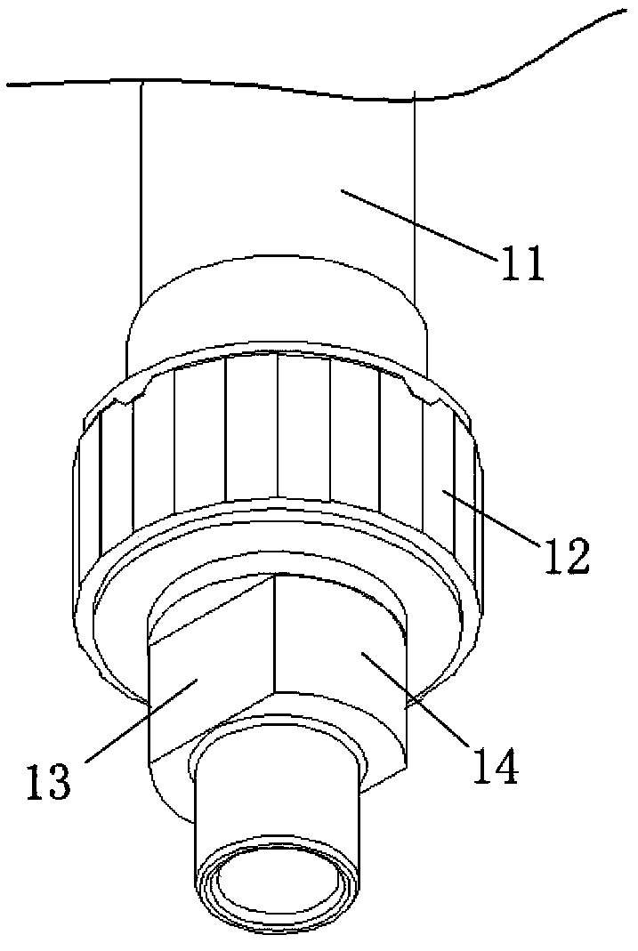
Active Publication Date: 2013-11-27
杭州新世宝电动转向系统有限公司
View PDF8 Cites 0 Cited by
  • Summary
  • Abstract
  • Description
  • Claims
  • Application Information

AI Technical Summary

Problems solved by technology

As a result, the phase deviates from the required position when the magnetic coil is magnetized, which affects the linearity of the sensor output signal

Method used


Image

  • Gap eliminating type magnetizing clamp
  • Gap eliminating type magnetizing clamp
  • Gap eliminating type magnetizing clamp

Examples


Embodiment Construction

[0029] The present invention will be further described below in conjunction with accompanying drawing.

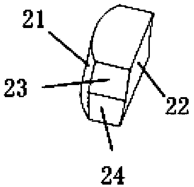
[0030] refer to Figure 3-13 : Gap-eliminating magnetizing fixture, comprising a slider 2, a support 3, and an extruded part 4, the support 3 has a cavity 31 for the input shaft 11 to extend into, and the upper end of the support 3 has a The slot 32 matched with the slider 2, the slot 32 includes a square slot 321 at the upper end and a dovetail slot 322 at the lower end of the square slot 321, the angle between the side and the bottom of the dovetail slot 322 is α, and the slot 32 matching slider 2, its side includes the upper vertical surface 23 and the lower inclined surface 24, the angle between the inclined surface 24 and the horizontal plane is α; the outer edge surface 21 of the slider 2 is from bottom to top and inward Inclined, the inclination angle of the outer edge surface 21 is θ, the extruded part 4 is supported on the upper end of the outer edge surface 21 of...


PUM


Abstract

The invention relates to a gap eliminating type magnetizing clamp, comprising a sliding block, a support, and an extrusion piece. The support has a cavity for an input shaft to extend; grooves matched with the sliding block are arranged at the both ends of the upper end of the support; the outer end surface of the sliding block is inclined inwards from bottom to top; the extrusion piece is supported at the upper end of the outer edge surface of the sliding block; the sliding block approaches to the middle by extruding the extrusion piece downwards, so that a mechanical flat opening on the input shaft is clamped; and the inner edge surface of the sliding block at a clamping state is tightly adhered to a limiting plane of the mechanical flat opening. The invention provides the magnetizing clamp can automatically eliminate a gap between a work piece and the magnetizing clamp, can automatically center a phase of a magnetic ring, and is used for improving the sensor properties and ensuring the sensor consistency.

Description

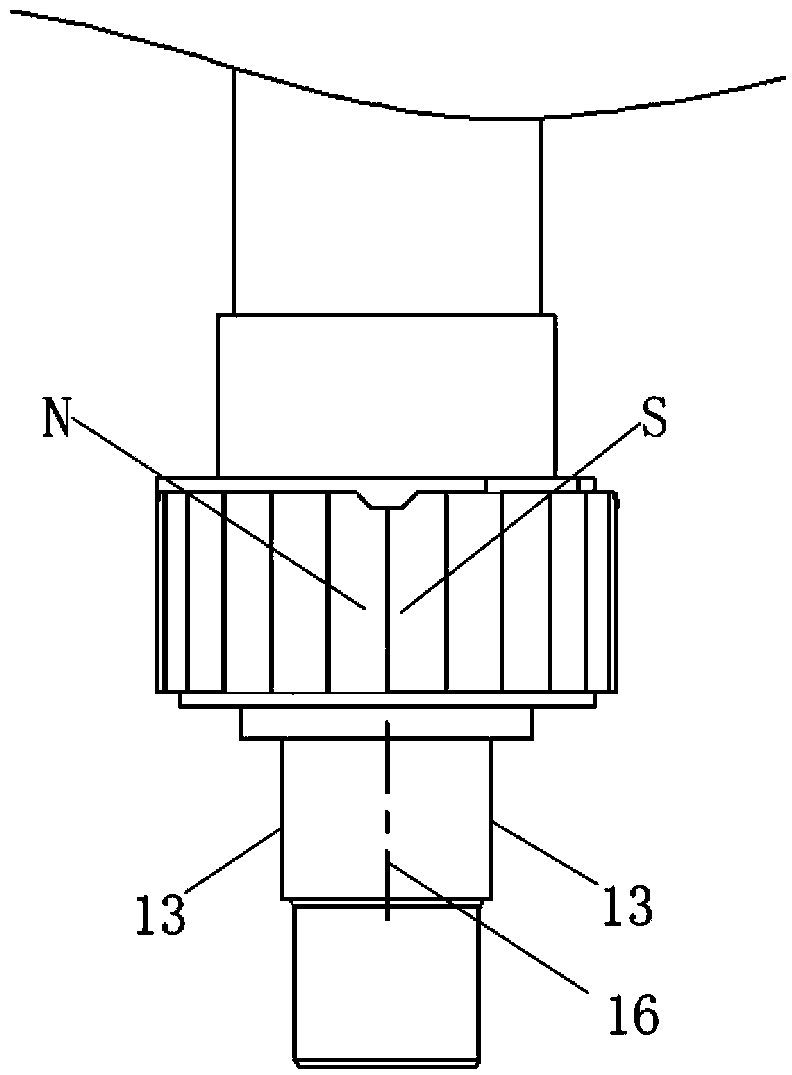
technical field [0001] The invention relates to a magnetizing fixture for a magnetic coil of an EPS Hall type torque sensor. Background technique [0002] The magnetic coil, as the magnetic field generating source of the EPS Hall torque sensor, its working principle determines that the magnetic coil must be connected with the input shaft including the mechanical flat mouth as a whole, and then the magnetizing coil on the workbench will carry out the magnetic coil. For multi-pole magnetization, the NS pole center position of the magnetic coil must be aligned with the center position of the mechanical flat mouth after magnetization. [0003] Figure 1-Figure 2 It is a structural schematic diagram of a magnetic coil assembly, which includes an input shaft 11 and a magnetic coil 12 mounted on the input shaft 11. The magnetic coil 12 is magnetized by a magnetizing coil located on the workbench. After magnetization, the magnetizing coil The NS pole phase center of the magnetic co...

Claims


Application Information

Patent Timeline
Patent Type & Authority Patents(China)
IPC IPC(8): H01F13/00
Inventor 斯祖兴蔡黎明周珑
Owner 杭州新世宝电动转向系统有限公司
Learn More