

Method to assign a customer premises equipment to a subscriber's data record, demarcation point unit, and network element
A technology of customer premises equipment and subscriber data, applied in electrical components, call branch offices, transmission systems, etc., can solve problems such as time-consuming, troublesome, and error-prone registration procedures
- Summary
- Abstract
- Description
- Claims
- Application Information
AI Technical Summary
Problems solved by technology
Method used
Image

Examples
Embodiment Construction
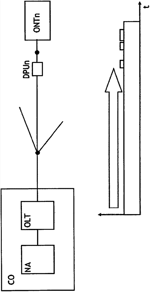
[0016] figure 1 Both a telecommunications network and a diagram representing signal flow therein are shown.
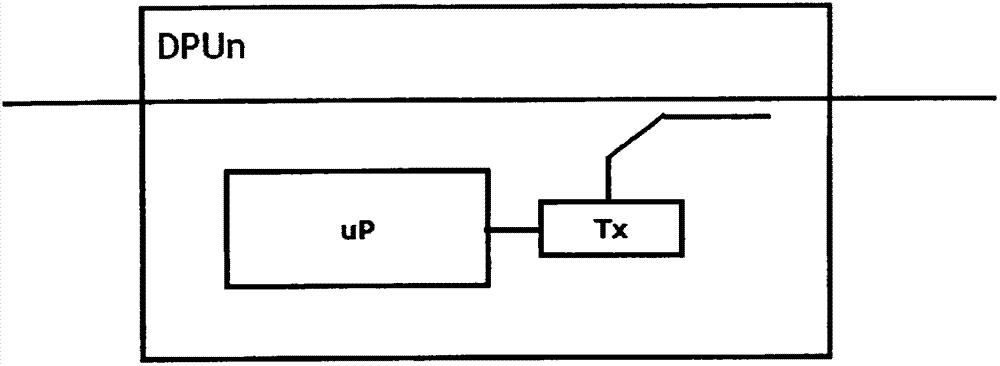
[0017] The telecommunications network comprises a central office CO, an access network (not shown), a demarcation point unit DPUn representing one of a plurality of network termination units, and an optical network termination unit ONTn representing a subscriber's customer premises equipment .
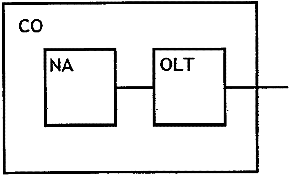
[0018] The central office CO is shown here as comprising an optical line termination unit OLT and a network analyzer NA.
[0019] The optical line termination unit OLT performs the conversion between the optical part and the electrical part and performs transmission technology functions such as adjusting power levels.
[0020] Network analyzers NA perform some types of network operations tasks.
[0021] It is to be noted that in practical implementations the network analyzer NA as described above is usually spatially separated from the optical line termination unit OLT and i...
PUM
 Abstract
Description
Claims
Application Information