Bone filler conveying sleeve

A technology of bone filler and delivery tube, which is applied in the direction of catheter, surgery, dilator, etc., can solve the problems of heavy economic burden, long operation time, and many instruments used by patients, so as to reduce the economic burden, reduce pain, and reduce complications. The effect of the incidence of

Active Publication Date: 2012-11-21
NINGBO HICREN BIOTECH
View PDF6 Cites 21 Cited by
  • Summary
  • Abstract
  • Description
  • Claims
  • Application Information

AI Technical Summary

Problems solved by technology

This method has cumbersome steps, long operation time,

Method used


Image

  • Bone filler conveying sleeve
  • Bone filler conveying sleeve
  • Bone filler conveying sleeve

Examples


Embodiment 1

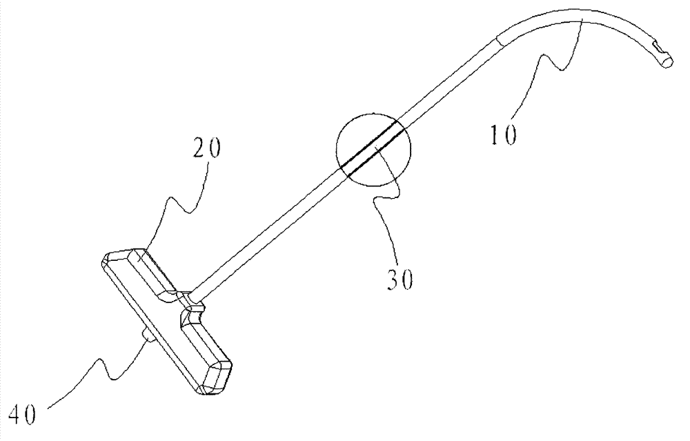
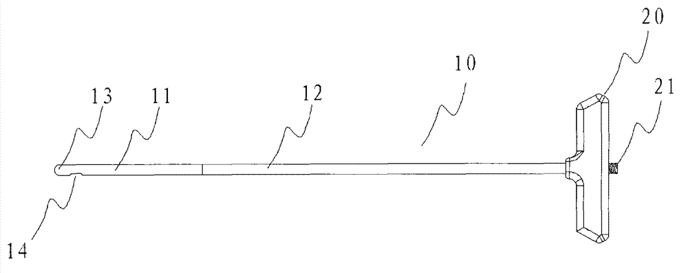
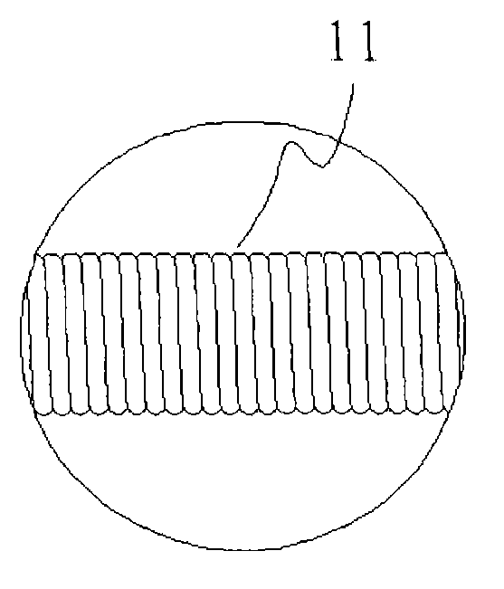
[0038] Such as figure 1 As shown in -3, a bone filler delivery sleeve includes a delivery tube 10 and a delivery handle 20, wherein the distal part of the delivery tube 10 is a flexible tube 11, and the proximal part of the delivery tube 10 is a rigid tube 12. The proximal end of the flexible tube 11 is fixedly connected to the distal end of the rigid tube 12 (such as glued, heat welded, riveted, screwed, etc.), and the proximal end of the rigid tube 12 is connected to the delivery handle 20 Fixed connection, the delivery handle 20 has a Luer connector 21 (for connecting with a bone filler injection device), the end 13 of the delivery tube 10 is closed, and the side wall of the flexible tube 11 has one or more holes 14. The bone filler delivery sleeve further includes a sheath core 30 slidably inserted inside the delivery tube 10, the proximal end 32 of the sheath core 30 is fixedly connected with an adjustment handle 40, and the sheath core 30 The distal end portion is bent ...

Embodiment 2

[0043] Such as Figure 8-1 As shown in 0, a bone filler delivery sleeve includes a delivery tube 10 and a delivery handle 20, wherein the distal part of the delivery tube 10 is a flexible tube 11, and the proximal part of the delivery tube 10 is a rigid tube 12 , the proximal end of the flexible tube 11 is fixedly connected to the distal end of the rigid tube 12 (such as glued, heat welded, riveted, screwed, etc.), and the proximal end of the rigid tube 12 is fixed to the delivery handle 20 The delivery handle 20 has a Luer connector 21 (for connecting with a bone filler injection device), the end 13 of the delivery tube 10 is not closed, and the bone filler delivery sleeve also includes a slidably inserted The sheath core 30 inside the delivery tube 10, the proximal end 32 of the sheath core 30 is fixedly connected to an adjustment handle 40, and the distal part of the sheath core 30 is bent at a fixed angle to form a fixed bending section of the sheath core 30 31, the end 3...

Embodiment 3

[0046] Such as Figure 8-1 As shown in 0, a bone filler delivery sleeve includes a delivery tube 10 and a delivery handle 20, wherein the distal part of the delivery tube 10 is a flexible tube 11, and the proximal part of the delivery tube 10 is a rigid tube 12 , the proximal end of the flexible tube 11 is fixedly connected to the distal end of the rigid tube 12 (such as glued, heat welded, riveted, screwed, etc.), and the proximal end of the rigid tube 12 is fixed to the delivery handle 20 connection, the delivery handle 20 has a luer connector 21 (for connection with a bone filler injection device), the end 13 of the delivery tube 10 is not closed, preferably on the side of the flexible tube section 11 at the distal end of the delivery tube 10 The wall has one or more holes 14, and the bone filler delivery sleeve also includes a sheath core 30 slidably inserted inside the delivery tube 10, and a proximal end 32 of the sheath core 30 is fixedly connected to an adjustment hand...


PUM

PropertyMeasurementUnit
Bending angleaaaaaaaaaa
Diameteraaaaaaaaaa

Abstract

The invention relates to a bone filler conveying sleeve which comprises a conveying tube, a conveying tube handle and a sheath core. A flexible tube is arranged at a far end of the conveying tube, a rigid tube is arranged at a near end of the conveying tube, a near end of the flexible tube is fixedly connected with a far end of the rigid tube, a near end of the rigid tube is fixedly connected with the conveying tube handle, the sheath core is slidably inserted into the conveying tube, a near end of the sheath core is fixedly connected with an adjusting handle, and a far end of the sheath core is bent to form a fixed angle which is a fixed bent section of the sheath core. The far end of the conveying tube of the bone filler conveying sleeve is provided with the flexible tube, and the sheath core with the fixed angle formed at the far end is inserted into the conveying tube, so that the purpose of controlling the bending degree of the far end of the conveying tube can be achieved by controlling the relative positions of the fixed bent section of the sheath core and the flexible tube at the far end of the conveying tube, and the bone filler conveying sleeve is convenient to operate, simple in structure and low in cost.

Description

technical field [0001] The present invention relates to a bone filler delivery sleeve, in particular to a bone filler delivery sleeve used in percutaneous vertebroplasty (PVP) or percutaneous kyphoplasty (PKP). Background technique [0002] Vertebral compression fractures caused by osteoporosis are more common in the elderly, and with the deepening of aging, the number of patients suffering from this disease is also increasing rapidly, and percutaneous vertebroplasty (PVP) or percutaneous vertebral body Kyphoplasty (PKP) played an irreplaceable role in it. At present, bone filler delivery sleeves are widely used in vertebroplasty. Under the monitoring of imaging equipment, fillers (such as bone cement) are injected into the cancellous bone space of the vertebrae with the help of external force to restore the height of the vertebral body and enhance The strength and stability of the vertebral body, relieve the pain of the patient's back, so as to treat the compression fractu...

Claims


Application Information

Patent Timeline
IPC IPC(8): A61M25/00A61M29/02A61L29/02A61L29/04
Inventor 吕世文汪宇毛克亚信朝华
Owner NINGBO HICREN BIOTECH
Why Eureka
Try Eureka