Artery puncture device
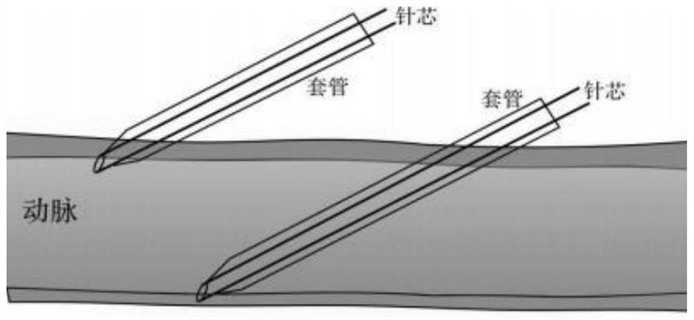
A technique of arterial puncture and pulse, applied in the direction of puncture needle, puncture needle, cardiac catheter, etc., can solve the problems of sticking to the wall, failure of catheter placement, failure of catheter placement, etc.
- Summary
- Abstract
- Description
- Claims
- Application Information
AI Technical Summary
Problems solved by technology
Method used
Image
Examples
Embodiment 1
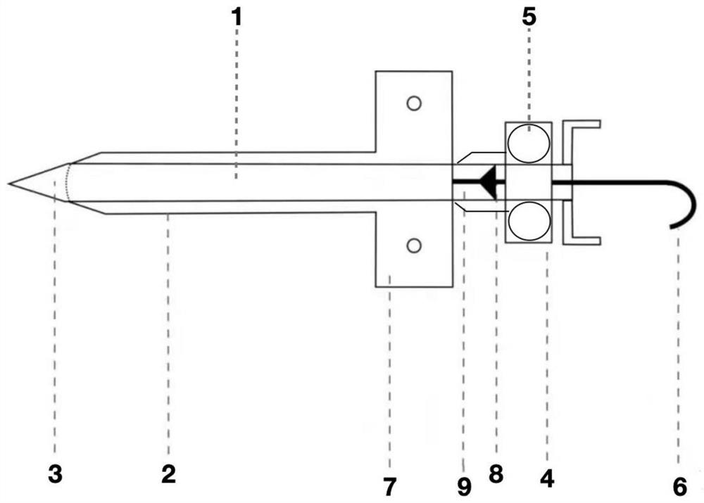
[0052] Embodiment 1: as figure 2 An arterial puncture needle is shown, including a needle core 1, a guide wire 6 in the needle core, and a cannula 2 sleeved on the outside of the needle core. The needle core 1 is a hollow structure, which is slightly longer than the needle sheath 2 by 0.1 ~0.2 cm, the guide wire 6 is fixed in the cavity of the needle core through the one-way valve 8, and the valve 8 is preferably made of sterile silicone rubber, which plays the role of fixing the guide wire 6 and preventing the backflow of blood. The end of the needle core 1 away from the needle 3 is fixed with a handle 4, and the needle core between the needle cover 2 and the handle 4 is provided with a transparent groove 9 for observing the return of blood. After the blood is returned, the guide wire can be sent. The body length of the needle core 1 is 4-5cm, the outer diameter of the hollow structure is 0.12-0.15cm, the inner diameter is 0.04-0.06cm, most preferably 0.048cm, and the mater...
Embodiment 2
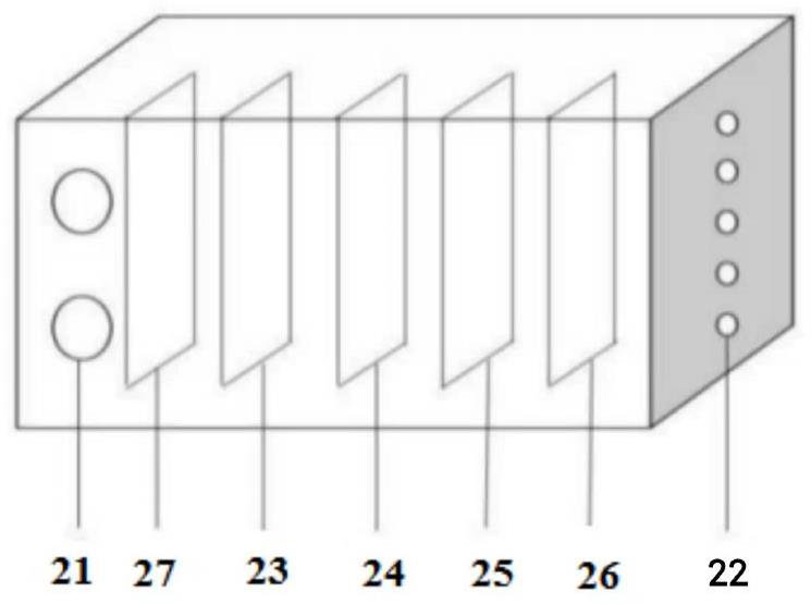
[0053] Embodiment 2: as image 3 The infrared pulse sensor shown is a rectangular parallelepiped with a size of 1 × 2 cm, powered by a button battery, and there are two magnetic sheets 21 on the bottom side with a diameter of 1 cm, which are suitable for the magnetic stickers 5; there are 5 indicator lights on the top. twenty two. like Figure 5 The connection method of the indicator light 22 is shown, in which R1 is the sampling resistor, which can convert the current into voltage, R2~R6 are the current limiting (protection) resistors, U is the total circuit voltage, preferably 3V; U1~U5 are The voltage shared by the two ends of each parallel branch circuit indicator light is preset with different voltage values U1>U2>U3>U4>U5 through the sliding rheostat, preferably U1=2.20V; U2=2.05V; U3=1.90V; U4 = 1.75V; U5 = 1.60V. According to this connection method, the stronger the current signal, the more the number of indicator lights, and the easier the indicator light on the ...
PUM
 Abstract
Description
Claims
Application Information
 - R&D
- Intellectual Property
- Life Sciences
- Materials
- Tech Scout
- Unparalleled Data Quality
- Higher Quality Content
- 60% Fewer Hallucinations
Browse by: Latest US Patents, China's latest patents, Technical Efficacy Thesaurus, Application Domain, Technology Topic, Popular Technical Reports.
© 2025 PatSnap. All rights reserved.Legal|Privacy policy|Modern Slavery Act Transparency Statement|Sitemap|About US| Contact US: help@patsnap.com


