Processing device for double-center hole punching of common lathe

A technology of ordinary lathes and processing devices, applied in boring/drilling devices, metal processing equipment, manufacturing tools, etc., can solve the problem of low coaxiality accuracy of the center holes at both ends, increase the processing time of shaft parts, and students have to To solve the problem, achieve the effect of reducing processing cost, improving coaxiality accuracy, and expanding the scope of use

Inactive Publication Date: 2012-11-21
GUANGXI UNIV
View PDF7 Cites 16 Cited by
  • Summary
  • Abstract
  • Description
  • Claims
  • Application Information

AI Technical Summary

Problems solved by technology

In the process of teaching and practice and the actual production of the factory, most of the machining process of some shaft parts is to use two U-turn clamping methods to process the center hole. After two clamping, it will bring two positioning errors. The error caused by one clamping is large, so that the accuracy of the coaxiality of the processed center holes at both ends is not high, and the two clampings will increase the processing time of shaft parts, and the efficiency is not high. Doesn't get better exercise in practice

Method used


Image

  • Processing device for double-center hole punching of common lathe
  • Processing device for double-center hole punching of common lathe
  • Processing device for double-center hole punching of common lathe

Examples


Embodiment Construction

[0030] The present invention will be further described below in conjunction with the accompanying drawings.

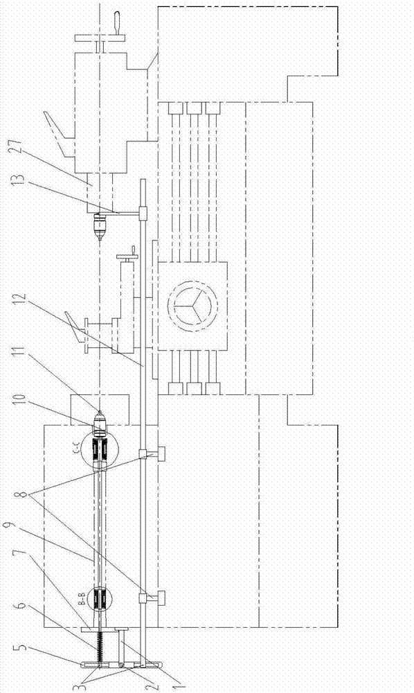
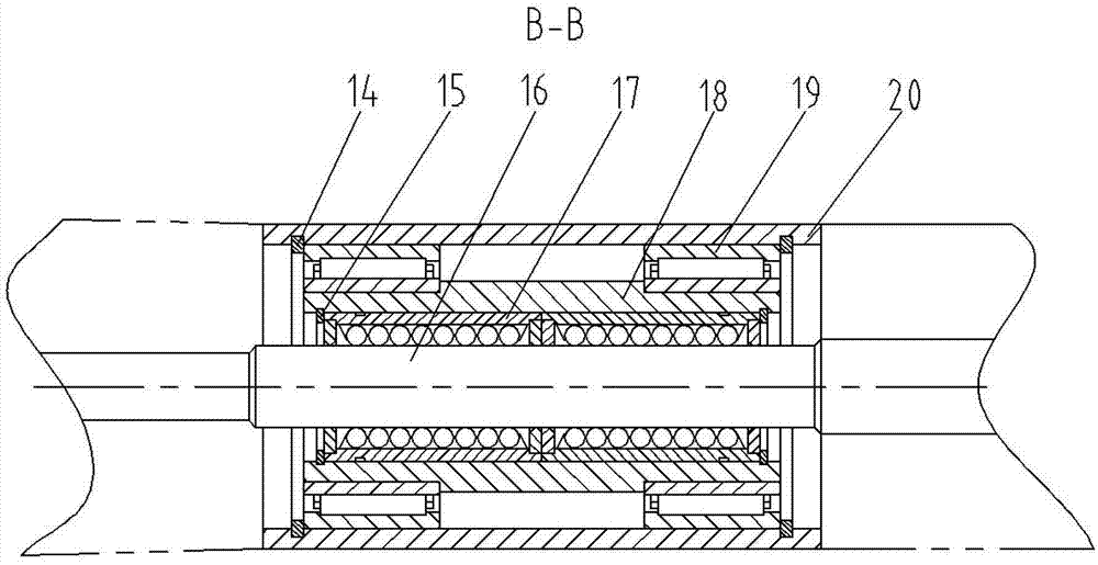
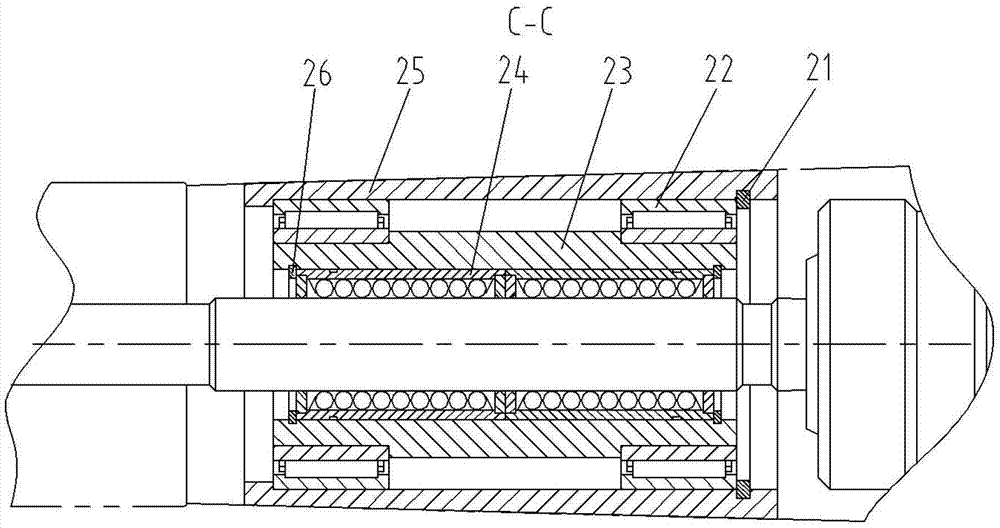
[0031] The present invention is a processing device for making double center holes on an ordinary lathe, which consists of a proportional reversing feed device, two groups of shaft hole feed devices placed in the main shaft hole 9, a drill chuck connecting rod 16, a drill chuck 10 and a center drill. 11, the main shaft is a part of the lathe itself, driven by the lathe motor through the transmission system. The drill chuck connecting rod 16 is a stepped shaft-type connecting rod. One end of the Morse taper is connected to the drill chuck 10, and the other end is connected to the fork 5 through the end conical pin 3. The front end of the drill chuck connecting rod 16 passes through the drill chuck. Chuck 10 is installed with center drill 11, and the front and rear parts of drill chuck connecting rod 16 are respectively equipped with a group of shaft hole feeding devices...


PUM


Abstract

The invention discloses a processing device for double-centre hole punching of a common lathe. The processing device comprises a proportional reversing feeding device, two groups of shaft hole feeding devices arranged in main shaft holes, a drill chuck connecting rod, a drill chuck and a central drill, wherein the central drill is arranged at a front end of the drill chuck connecting rod through the drill chuck; two groups of shaft hole feeding devices are respectively arranged at front and back parts of the drill chuck connecting rod; each group of the shaft hole feeding devices structurally comprises a liner sleeve, needle rolling bearings, an shaft sleeve and a linear ball bearing which are arranged in the main shaft holes, wherein the linear ball bearing is tightly sleeved on the drill chuck connecting rod; the shaft sleeve is tightly sleeved on the linear ball bearing; the needle rolling bearings are respectively arranged at two ends of the shaft sleeve; and the liner sleeve tightly arranged in the main shaft hole is sleeved on the needle rolling bearing; and one end of the proportional reversing feeding device is connected with a rear end of the drill chuck connecting rod, and the other end of the proportional reversing feeding device is connected with a tail seat of a lathe main body for arranging the drill chuck. By adopting the processing device to punch centre holes at two ends of parts, such as shafts, clamping time can be reduced, efficiency can be improved, precision can be improved, the precision of coaxiality of processing workpieces can be ensured, and meanwhile, workpieces with central holes with different depth and different types at a left end and a right end can be processed through a left central drill and a right central drill with different-ratio feeding rate and feeding volume.

Description

technical field [0001] The invention relates to a processing tool, in particular to a processing device for drilling double center holes on a common lathe. Background technique [0002] Shaft parts are one of the common typical parts. According to the different structural forms of shaft parts, it can generally be divided into three types: optical shaft, stepped shaft and special-shaped shaft; or divided into solid shaft and hollow shaft. They are used in machines to support transmission parts such as gears and pulleys to transmit torque or motion. Horizontal lathe machining shaft parts generally go through several processes such as turning the end face, drilling the center hole, determining the overall length and then drilling the center hole. In the process of teaching and practice and the actual production of the factory, most of the machining process of some shaft parts is to use two U-turn clamping methods to process the center hole. After two clamping, it will bring t...

Claims


Application Information

Patent Timeline
Patent Type & Authority Applications(China)
IPC IPC(8): B23B43/02
Inventor 王勇王建红钟晓虹王小纯范才翼覃石
Owner GUANGXI UNIV
Why Eureka
Try Eureka