Differential anti-overlap micromotion mechanism of rotor spinning machine

A rotor spinning machine, anti-overlapping technology, applied in the field of spinning machinery and equipment, can solve the problems of reducing the service life of the yarn pressing roller, affecting the yarn quality of the yarn, and unbalanced yarn holding force, etc., to improve The effect of extending the service life, the interval time, and reducing the degree of wear

Inactive Publication Date: 2014-07-23
上海捷春进出口贸易有限公司
View PDF7 Cites 0 Cited by
  • Summary
  • Abstract
  • Description
  • Claims
  • Application Information

AI Technical Summary

Problems solved by technology

This not only reduces the service life of the yarn pressing cot rollers, but also causes the unbalanced holding force of the yarn pressing cots on the yarn, which seriously affects the yarn quality of the yarn and brings economic losses to customers

Method used


Image

  • Differential anti-overlap micromotion mechanism of rotor spinning machine
  • Differential anti-overlap micromotion mechanism of rotor spinning machine
  • Differential anti-overlap micromotion mechanism of rotor spinning machine

Examples


Embodiment Construction

[0028] Below in conjunction with accompanying drawing and specific embodiment, further explain content of the present invention:

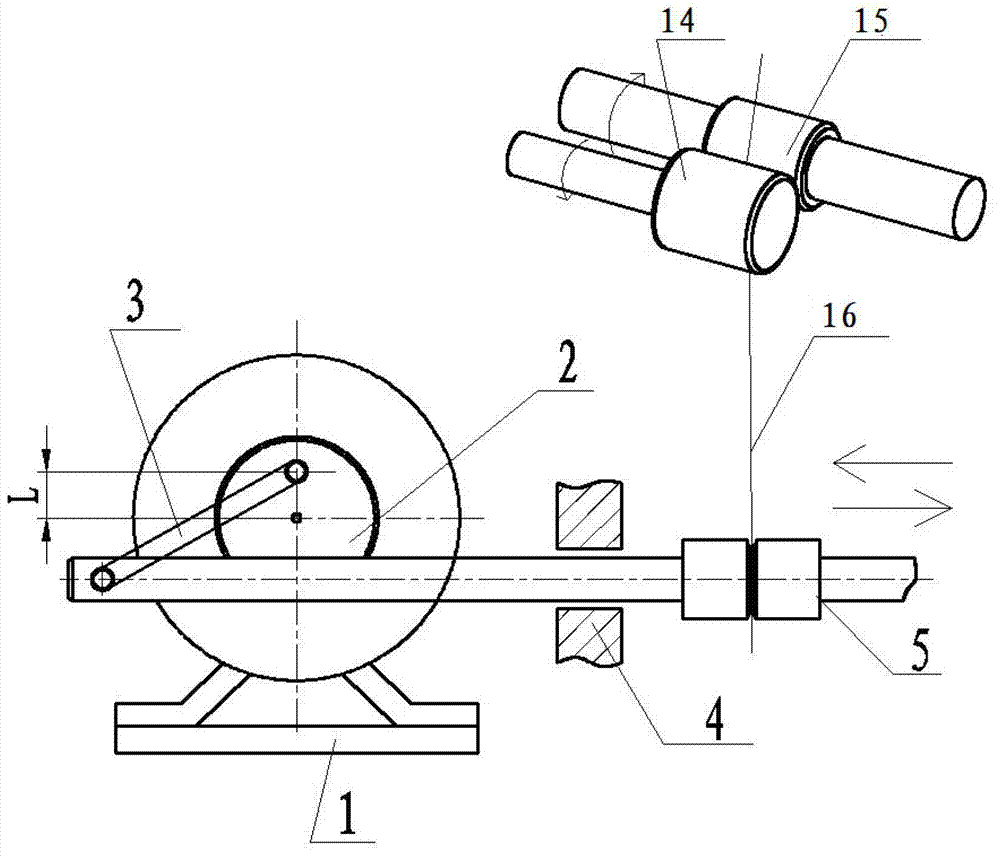
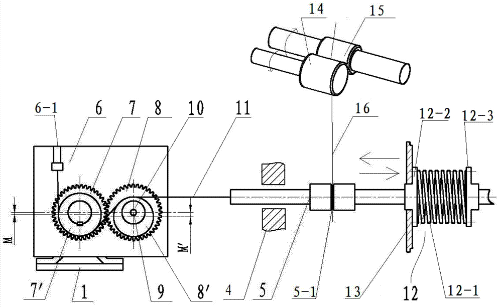
[0029] Such as figure 2 As shown, a differential anti-overlap micro-motion mechanism of a rotor spinning machine includes a micro-motion rod 5 horizontally arranged through a guide hole 4, and above the micro-motion rod is a yarn pressing roller 14 and a yarn delivery roller 15, The yarn 16 is closely attached to the groove 5-1 on the micro-moving rod and is drawn upward by the yarn drawing roller and the yarn pressing roller. The right end of the micro-moving rod passes through the wallboard 13, and an elastic Tensioning device 12, the left side of the micro-movement rod is provided with a micro-motion seat 6, and the speed reducer 1 and two left and right gears arranged side by side and meshing with each other are installed on the micro-motion seat. The other gear is a driven gear, and the driven gear 8 is installed on the micro-movement seat 1...


PUM


Abstract

The invention relates to a differential anti-overlap micromotion mechanism of a rotor spinning machine. The differential anti-overlap micromotion mechanism comprises a horizontally-arranged micromotion rod, wherein a right end of the micromotion rod penetrates through a wall plate and an end head of the micromotion rod is provided with an elastic tension device; the left side of the micromotion rod is provided with a micromotion seat, the micromotion seat is installed with a reducer and a left gear and a right gear which are arranged in parallel and mutually engaged; the gear coaxially connected with the reducer is a driving gear and the other gear is a driven gear; end faces of the two gears on the same side are respectively provided with a driving eccentric boss with an eccentric arm of M and a driven eccentric boss with the eccentric arm of M'; a fixed seat is installed at a top end of the micromotion seat on the left side upper part of the left gear, and the lower part of the fixed seat is connected with a micromotion belt; the micromotion belt is intertwined from the lower end of the left eccentric boss to the upper end of the right eccentric boss and is fixedly connected with the left end of the micromotion rod.

Description

technical field [0001] The invention relates to a novel yarn-drawing micro-motion mechanism of a rotor spinning machine, which belongs to the technical field of spinning machinery and equipment. Background technique [0002] In the spinning process of the rotor spinning machine, after the fiber is twisted into yarn by the rotor, it passes through the false twist disk and the twist arrester in the yarn delivery tube, and is drawn out by the yarn delivery roller and the yarn pressure roller, and finally by the winding The roller drives the bobbin to be wound into a bobbin. There is a yarn-drawing micro-motion mechanism between the yarn-drawing tube outlet and the yarn-drawing roller. Such as figure 1 As shown, the fretting yarn guide mechanism has a reducer 1, and a transmission wheel 2 is installed on its shaft, and an eccentric hole with an eccentricity L is provided on the end surface of the transmission wheel, which is used to connect the joint bearing 3, and the other j...

Claims


Application Information

Patent Timeline
Patent Type & Authority Patents(China)
IPC IPC(8): D01H4/08
Inventor 张志李健伟王青考
Owner 上海捷春进出口贸易有限公司
Why Eureka
Try Eureka