Flow-volume regulator

A flow regulator and regulator technology, applied in flow control, control/regulation systems, instruments, etc., can solve the problems of water outlet, manufacturing cost, complicated flow regulator, etc., and achieve the effect of saving space and compact structure

Active Publication Date: 2012-11-21
NEOPERL
View PDF9 Cites 10 Cited by
  • Summary
  • Abstract
  • Description
  • Claims
  • Application Information

AI Technical Summary

Problems solved by technology

Therefore, the flow regulator known from DE-OS 21 31 117 is relatively bulky and cannot be installed in narrow space conditions, for examp

Method used


Image

  • Flow-volume regulator
  • Flow-volume regulator
  • Flow-volume regulator

Examples


Embodiment Construction

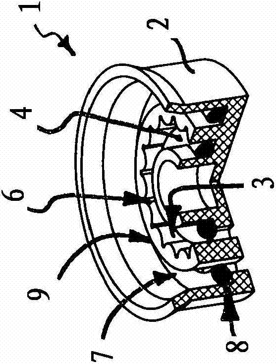
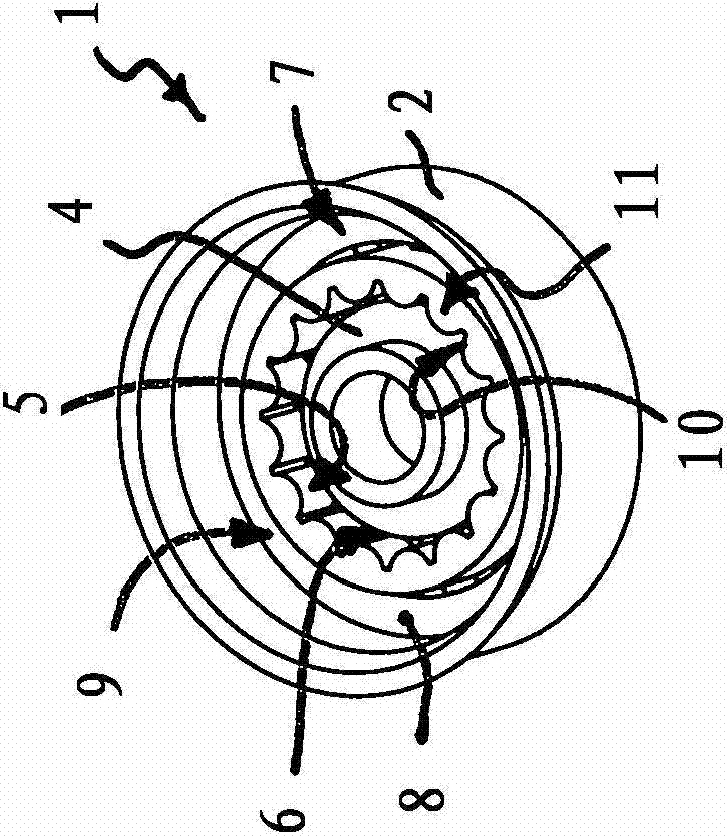
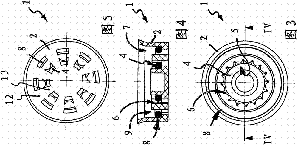
[0030] exist Figures 1 to 9 Different embodiments 1 , 110 of the flow regulator are shown in FIGS. 10 to 14 . The flow regulator 1 , 110 has a regulator housing 2 which can be inserted into a sanitary water line, for example into a water outlet of a sanitary drain. The regulator housing 2 of the flow regulator 1 , 110 has a regulator annular channel 3 in which an annular throttle body 4 made of elastic material is arranged. The elastic throttle body 4 delimits a control gap 6 between itself and the channel wall with the adjustment profile 5 , the flow cross-section of which can be changed by the throttle body 4 being deformed by the pressure difference created during the flow. . As the pressure increases, the throttle body 4 made of elastic material deforms towards the adjusting profile 5 so that the flow cross-section of the control gap 6 becomes narrower and narrower, so that the maximum flow capacity is limited to a defined value independently of the pressure .

[0031...


PUM


Abstract

The invention relates to a flow-volume regulator having a regulator housing which has at least one regulator ring channel which contains an annular flow restrictor made of elastic material which bounds, between itself and a channel wall that bears a regulatory profiling, a control gap for which it is possible to alter the passage cross section by means of the flow restrictor, which deforms under the pressure difference that forms during the flow, and also having at least one valve which has a valve body which moves under the pressure of the flowing medium from an open position counter to a restoring force into a closed position, in which closed position the valve body closes off at least one valve opening. In order to be able to make the flow-volume regulator according to the invention compact and also to mount it in space-saving fashion under confined circumstances, the invention provides for the valve body to be provided in a valve ring channel in the regulator housing which valve ring channel has at least one valve opening in the region of its channel base, for the valve body to be of annular design and to made from elastic material, and for the annular valve body to deform under the pressure of the flowing medium such that the valve body moves from the open position counter to the restoring force of the inherent elasticity of the elastic material used for the valve body into the closed position.

Description

technical field [0001] The invention relates to a flow regulator having a housing with at least one regulator annular channel in which an annular throttle body made of elastic material is arranged, the throttle The fluid delimits a control gap between itself and the channel wall with the adjustment profile, the flow cross-section of which can be changed by means of a throttle body deformed under the pressure difference created during the flow; and the flow regulator There is at least one valve having a valve body which is moved under the pressure of the medium through which it flows against a restoring force from an open position into a closed position in which the valve body closes at least one valve opening. Background technique [0002] from DE-OS 21 31 117 Figure 6 A flow regulator of the type mentioned at the outset is already known from . The known flow regulator has a regulator housing with a regulator annular channel, in which an annular throttle body made of elast...

Claims


Application Information

Patent Timeline
IPC IPC(8): F16K17/22
CPCG05D7/012B05B1/3006B05B12/088E03C2001/026Y10T137/7792F16K15/14F16K47/08
Inventor S·特威切特
Owner NEOPERL
Why Eureka
Try Eureka