Optical diaphragm, light guide plate, combination method thereof and backlight module

A technology of optical diaphragm and backlight module, which is applied in the direction of optics, light guides, optical components, etc., and can solve problems such as poor assembly, diaphragm displacement, and affecting the display effect of display devices

Inactive Publication Date: 2012-11-21
BOE TECH GRP CO LTD +1
View PDF8 Cites 21 Cited by
  • Summary
  • Abstract
  • Description
  • Claims
  • Application Information

AI Technical Summary

Problems solved by technology

[0003] The backlight module generally includes: a light guide plate, a diffusion sheet, a prism sheet and other optical films (referred to as the film), the gap between the films (that is, between the light guide plate and the optical film, and between the optical films) The unevenness of the gap) will lead to poor picture display quality, and the larger the size of the TV, the more difficult it is to control the gap between the diaphragms. At present, the combination of the light guide plate and the diaphragm is still mechanically fixed. Too large, poor assembly, heat, vibration, easy to cause displacement or wrinkles between the diaphragms, resulting in poor picture quality and affecting the display effect of the display device

Method used


Image

  • Optical diaphragm, light guide plate, combination method thereof and backlight module
  • Optical diaphragm, light guide plate, combination method thereof and backlight module
  • Optical diaphragm, light guide plate, combination method thereof and backlight module

Examples


Embodiment

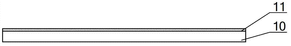
[0036] An embodiment of the present invention provides an optical film 10, at least one surface of the optical film 10 is provided with a magnetic film layer 11 on part or all of the area; the magnetic film layer 11 is magnetic and made of a transparent magnetic material.

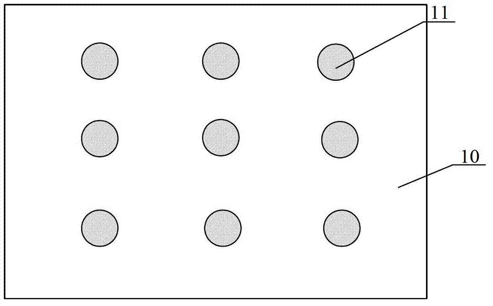
[0037] Such as figure 1 As shown, the magnetic film layer 11 can be covered on the entire surface of the optical film 10, or can be covered on the periphery of the optical film 10, or the middle area, such as figure 2 As shown, there are 9 circular magnetic film layers 11 arranged in the middle area of ​​the optical film 10, which is called 9-point method, and similarly there are 5-point method and 6-point method.

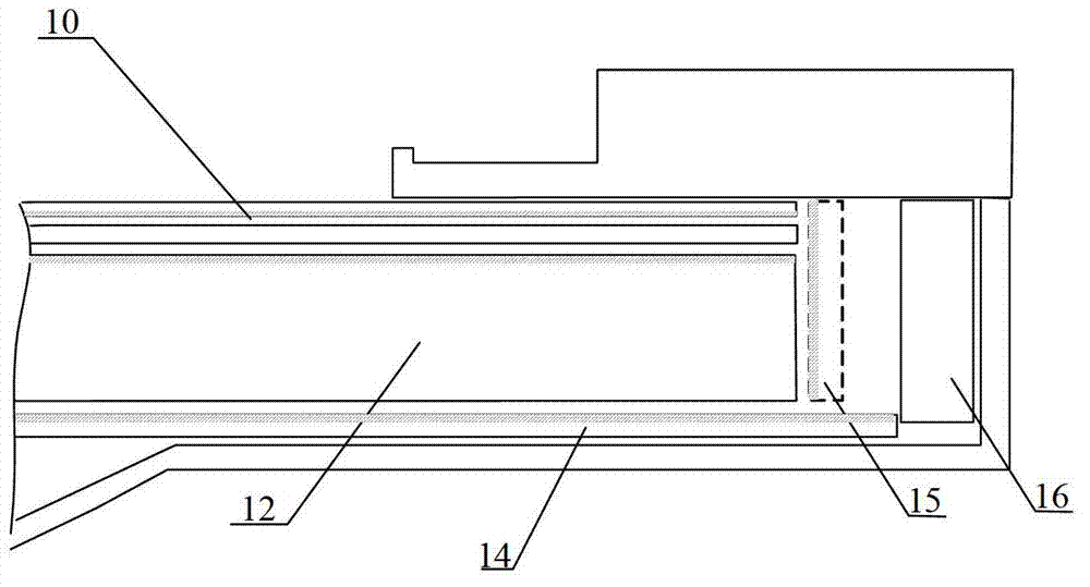
[0038] In the embodiment of the present invention, a magnetic film layer 11 is provided on the optical film 10, aiming to make the adjacent magnetic film layers 11 in the film to be combined mutually Attraction, so that the membranes to be combined are adsorbed together. Therefore, the optica...

Embodiment 2

[0067] The embodiment of the present invention also provides a combination method of the light guide plate and the optical film in the backlight module, such as Figure 5 As shown, the method includes:

[0068] 101. A magnetic film layer is provided, and the direction of the magnetic field of the magnetic film layer causes mutual attraction between the light guide plate and the optical film, wherein,

[0069] When the optical films to be combined are all located on one side of the light guide plate, a magnetic film layer is respectively provided on at least the light guide plate and the optical film farthest from the light guide plate,

[0070] When the optical films to be combined are respectively located on both sides of the light guide plate, at least magnetic film layers are respectively provided on the two optical films that are farthest apart;

[0071] 102 . Bond each optical film in the backlight module and the light guide plate together through the magnetic attraction...


PUM

PropertyMeasurementUnit
particle diameteraaaaaaaaaa

Abstract

The invention discloses an optical diaphragm, a light guide plate, a combination method of the optical diaphragm and the light guide plate, and a backlight module provided with the optical diaphragm and the light guide plate, and relates to the field of display, aiming at solving the displacement or the wrinkle of the diaphragm caused by the overlarge size of the diaphragm, the bad assembly, the heating deformation and the vibration, effectively reducing the probability of the bad screen display quality, and improving the display effect. Some parts or all parts of at least one of surfaces of the optical diaphragm are provided with magnetic diaphragm layers; and the magnetic diaphragm layers have the magnetism, and are made from transparent magnetic materials. The surface of the light guide plate is further provided with the magnetic diaphragm layer. The combination method of the optical diaphragm and the light guide plate in the backlight module comprises the following steps of: respectively arranging the magnetic diaphragm layers on the light guide plate and the optical diaphragm; and gluing each optical diaphragm with each light guide plate due to the magnetic attraction of the magnetic diaphragm layers.

Description

technical field [0001] The invention relates to the field of display technology, in particular to an optical film used in a backlight module, a light guide plate and a combination method thereof, and a backlight module provided with the optical film and the light guide plate. Background technique [0002] The backlight module is one of the key components of the liquid crystal display device. Since the liquid crystal itself does not emit light, the main function of the backlight module is to provide a uniform and high-brightness illuminant for the liquid crystal panel. The illuminant is converted into a surface luminous product with high brightness and uniform luminance through an effective light mechanism, so that the liquid crystal panel can display images normally. In addition to being used in LCD TVs and liquid crystal display devices, backlight modules can also be used in display devices that require backlights such as digital photo frames, electronic paper, and mobile p...

Claims


Application Information

Patent Timeline
Patent Type & Authority Applications(China)
IPC IPC(8): G02B5/02G02B5/04G02B6/00G02B1/11F21S8/00
Inventor 吴行吉许益祯张亮
Owner BOE TECH GRP CO LTD
Why Eureka
Try Eureka