Grease for electrical contact and slide electricity structure, power switch, vacuum circuit breaker, vacuum-insulated switchgear assembling method

A switchgear, vacuum insulation technology, applied in the direction of switchgear, switchgear setting, high-voltage air circuit breaker, etc., can solve the problems of increasing contact resistance, low conductivity passivation film, shortening service life, etc.

Inactive Publication Date: 2014-12-24
HITACHI IND EQUIP SYST CO LTD +1
View PDF10 Cites 0 Cited by
  • Summary
  • Abstract
  • Description
  • Claims
  • Application Information

AI Technical Summary

Problems solved by technology

[0007] Since the existing grease for electrical contacts contains azo-based additives, when it is applied to a silver-plated contact for the purpose of stabilizing the contact resistance, it reacts with the silver plating to form a low-conductivity passive grease. Film
Therefore, there are cases where the contact resistance increases with sliding
[0008] In addition, if a low-viscosity base oil is used, the service life will be shortened, so when it is applied to a power switch with a product service life of more than several decades, it is considered necessary to supply grease regularly every few years.

Method used


Image

  • Grease for electrical contact and slide electricity structure, power switch, vacuum circuit breaker, vacuum-insulated switchgear assembling method
  • Grease for electrical contact and slide electricity structure, power switch, vacuum circuit breaker, vacuum-insulated switchgear assembling method
  • Grease for electrical contact and slide electricity structure, power switch, vacuum circuit breaker, vacuum-insulated switchgear assembling method

Examples


Embodiment 1

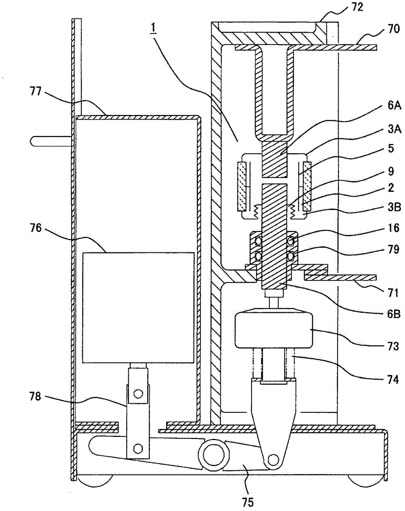
[0023] figure 1 An example of a vacuum circuit breaker will be shown as the first embodiment of the sliding conduction structure to which the grease for electrical contacts of the present invention is applied.

[0024] As shown in the figure, a vacuum circuit breaker generally includes: a vacuum valve 1 having at least one pair of contact points that can be brought into contact or separated from each other; a fixed-side terminal 70 and a movable-side terminal 71 connected to the vacuum valve 1; An insulating cylinder 72; an insulating operating rod 73 connected to the movable side electrode 6B of the vacuum valve 1; a wiping (wipe mechanism) mechanism 74 for applying contact force to the movable side electrode 6B and the fixed side electrode 6A of the vacuum valve 1; An operator 76 that generates an operating force; an operating lever 78 connected to the operator 76; a main lever 75 that connects the operating lever 78 to the wiping mechanism 74; and a housing 77 that accommod...

Embodiment 2

[0047] Figure 4 An example of a vacuum insulated switchgear as a second embodiment of the sliding current structure to which the grease for electric contacts of the present invention is applied is shown.

[0048] As shown in the figure, the vacuum insulated switchgear uses the solid insulator 30 to collectively cast the busbar bushing center conductor 41, the vacuum valve 1, the cable bushing center conductor 43, the earthing breaker bushing side fixed electrode 11, etc. , by combining with the movable electrode 12 of the grounding breaking part that moves linearly in the atmosphere, the grounding breaking part 10 that switches the on state, the grounding state and the disconnecting state is constituted. In addition, in this embodiment, for the sake of illustration, it is configured to be able to switch the three positions of on, ground, and disconnected, but if it is a switch with a slide conduction structure, it may also be configured to be able to switch between two positi...


PUM

PropertyMeasurementUnit
particle diameteraaaaaaaaaa

Abstract

A slide electricity structure according to the present invention uses grease for electrical contacts wherein contact resistance does not gradually increase even when exposed to sliding and lifetime is long, and has a silver-plated spring contact that contacts or separates by way of sliding and grease for electrical contacts that has been applied to the spring contact and contains perfluoropolyether oil having an average molecular weight between 2600 and 12500 as a base oil and PTFE having a primary particle diameter of 1 µm or less as a thickener.

Description

technical field [0001] The present invention relates to a lubricating grease for electric contacts, a sliding current structure, a switch for electric power, a vacuum circuit breaker, a vacuum insulated switchgear and an assembly method thereof. Background technique [0002] Patent Document 1 is known as a prior art related to grease for electric contacts and a sliding current-carrying structure to which the grease is applied. This Patent Document 1 describes that in order to provide a grease for electrical contacts that achieves a long-term stable lubricating effect and a contact with a lubricating effect, the main component of the lubricant contains polyα-olefin or fluid paraffin as a thickener. , the mixture using polybutene contains one or two kinds of mercaptobenzothiazole compounds and dibenzothiazole disulfide. [0003] In addition, Patent Document 2 describes that the electric contact is coated with 95 to 70% by weight of base oil excluding fluorine-based oil, and 5...

Claims


Application Information

Patent Timeline
Patent Type & Authority Patents(China)
IPC IPC(8): H01H1/36H01H33/66H01H11/00H02B13/00C10M169/02C10N40/14
CPCH01H3/62C10M169/02C10N2220/021H01H1/60H01H33/666C10M2213/0606C10M2213/0626C10N2240/20C10N2220/082H01H33/6606C10N2240/202C10N2250/10C10N2020/04C10N2020/06C10N2040/14C10N2050/10C10N2040/17Y10T29/49204
Inventor 佐藤隆佐藤和弘森田步土屋贤治菅野隆夫新田敏夫
Owner HITACHI IND EQUIP SYST CO LTD
Why Eureka
Try Eureka