
Tire testing apparatus having adjustable bead width

A bead width and testing machine technology, which is applied in the testing of automobile tires, mechanical equipment, vehicles, etc., can solve problems such as tire deformation and affect test results, and achieve the effect of simplifying construction and operation and expanding the range of travel.

Inactive Publication Date: 2012-11-21
MICRO POISE MEASUREMENT SYST
View PDF7 Cites 5 Cited by
  • Summary
  • Abstract
  • Description
  • Claims
  • Application Information

AI Technical Summary

Problems solved by technology

The force applied by the hydraulic actuator must also be sufficient to hold the center cone against the center groove of the upper rim, with sufficient pressure to flexibly connect the upper and lower rims so that rotational forces applied to the upper rim pass through with little slippage The center cone instead of the tire is transmitted to the lower rim, slippage may deform the tire and thus affect the test results

Method used


Image

  • Tire testing apparatus having adjustable bead width
  • Tire testing apparatus having adjustable bead width
  • Tire testing apparatus having adjustable bead width

Examples


Embodiment Construction

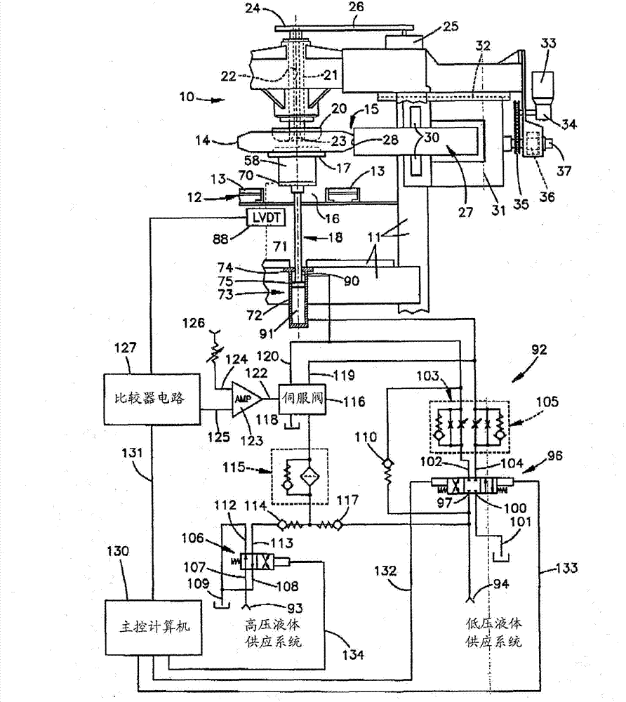
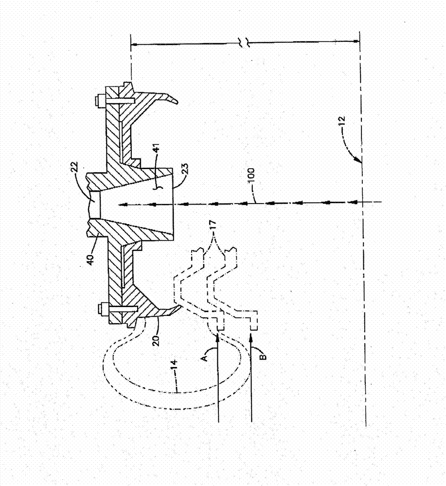
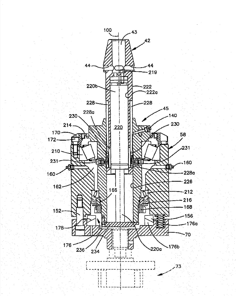
[0015] figure 1 A tire uniformity testing machine 10 is shown which includes a tire clamp / grip device constructed in accordance with the present invention. The testing machine 10 also includes a frame 11 supporting a conveyor 12 comprising a plurality of rollers 13 for transporting tires 14 to be tested to a testing station 15 . A detailed description of the conveyor 12 is found in US Patent No. 4,846,334, which is incorporated herein by reference in its entirety. Conveyor 12 includes an opening 16 sized both small enough to prevent tires from slipping through and large enough to pass a lower rim 17 , which is rotatably mounted on a vertically telescoping lower rim assembly 18 . The upper rim 20 is rotatably mounted on the upper part of the frame 11 through an upper rim spindle 21 . The upper rim 20 is opposite to the lower rim 17. During the test, the lower rim 17 is in the figure 1 In the extended position shown and in partial perspective view 2, the upper rim 20 and th...


PUM


Abstract

An adjustable width chuck assembly for a tire testing machine including upper and lower relatively movable rims by which a tire is clamped and held during a testing cycle. A pilot or nose cone forming part of one of the rims is gas pressure biased towards engagement with complementally formed structure on the other rim. The gas pressure bias is provided by a gas spring which can be replaced with gas springs of differing pressures in order to adjust the biasing force or, alternately, the gas spring can be removed from the chuck assembly and re-pressurized to a different level in order to change its biasing force. The use of a gas spring for providing the necessary biasing force expands the range of motion for the nose cone, thus allowing a given chuck assembly to accommodate tires having a wide range of bead widths.

Description

[0001] Related applications [0002] This application claims priority to US Provisional Patent Application No. 61 / 312,432, filed March 10, 2010, which is hereby incorporated by reference in its entirety. field of invention [0003] The present invention relates to tire testing. More particularly, the present invention relates to an apparatus and method for clamping tires having different bead widths in a testing machine such as a uniformity tester. Background technique [0004] While the invention is broadly applicable to a variety of tire testing rigs requiring quick clamping of tires, there are significant advantages to using the invention in tire uniformity testing machines. The tire uniformity testing machine generally includes an upper rim, a lower rim that can move vertically, and a conveyor that brings the tire to the middle of the upper and lower rims. A mechanism is provided to carry the tire and lift the lower rim through the opening of the conveyor to the upper...

Claims


Application Information

Patent Timeline
Patent Type & Authority Applications(China)
IPC IPC(8): G01M17/02
CPCG01M17/021G01M17/02Y10T279/12
Inventor 詹姆斯·沃尔布林克理查德·R·马图斯尼巴里·卡古尔德理查德·里格
Owner MICRO POISE MEASUREMENT SYST
Learn More