Pilot arc chopped wave control circuit and cutting machine

A technology for controlling circuits and maintaining arc cutting, which is applied in manufacturing tools, arc welding equipment, welding equipment, etc., and can solve the problem of non-fixed frequency of switching tube IGBT for chopping power, serious loss of gun electrodes and nozzles, and easy breakage of maintaining arc arc and other problems, to achieve the effect of solving the problem of arc starting and breaking, maintaining the stability of arc current and high success rate of arc starting

CN102794547AActive Publication Date: 2012-11-28SHENZHEN RILAND IND
8 Cites 7 Cited by

Patent Information

Authority / Receiving Office
CN · China
Patent Type
Applications(China)
Current Assignee / Owner
Publication Date
2012-11-28

Smart Images

  • Figure 1
    Figure 1
  • Figure 2
    Figure 2
Patent Text Reader

Abstract

The invention provides a pilot arc chopped wave control circuit and a cutting machine. The pilot arc chopped wave control circuit comprises a power switch device drive circuit for generating a pulse width modulation drive signal under low power grid input condition and limiting the current of a power switch tube, a differential amplification sampling circuit for sampling and amplifying the current under low power grid input condition, a current feedback loop control circuit for regulating the pulse width of the pulse width modulation drive signal according to the amplified current signal, and a pilot arc current reflowing circuit for reflowing the current to a main loop for transmission to a spraying nozzle of the cutting machine when the power switch tube is closed and the output negative terminal is positive, wherein the power switch device drive circuit, the differential amplification sampling circuit, the current feedback loop control circuit and the pilot arc current reflowing circuit are conductively connected in sequence. Ultramicrocrystal main transformer bias and pilot arc overcurrent protection are avoided, the success rate of arc starting is increased, the pilot arc current is stable, the arc cannot be broken, the small-current constant-current control is achieved, and the problems of arc starting and arc breaking under low power grid voltage input condition are solved; and meanwhile, the loss of the pilot arc and the pilot arc of the spraying nozzle is reduced, and the control circuit is long in service life, durable and reliable.
Need to check novelty before this filing date? Find Prior Art

Description

Technical field

[0001] The invention belongs to the field of arc-dimensioning control technology and cutting machine technology, and in particular relates to an arc-dimensioning chopper control circuit and a cutting machine.

Background technique

[0002] At present, in the non-high-frequency chopper arc maintenance control circuit, the arc maintenance current is set at about 18-20A, and the arc maintenance circuit generally uses the iron-chromium resistance coil voltage to judge the arc maintenance state, and opens the auxiliary exhaust valve to reduce the arc maintenance. stage air pressure, and use relays to switch on and off the arc-maintaining circuit. In this solution, the arc-maintaining resistance generates serious heat, and has high requirements for installation technology and heat dissipation. There are potential safety hazards when using the product for a long time. Adjustment, the circuit work is controlled by the gun switch, the output current adopts the curr...

Examples

Embodiment Construction

[0022] The technical solution of the present invention will be described in detail below in conjunction with the accompanying drawings.

[0023] like figure 1 and to figure 2 as shown in:

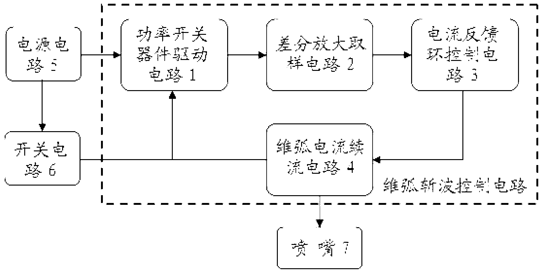
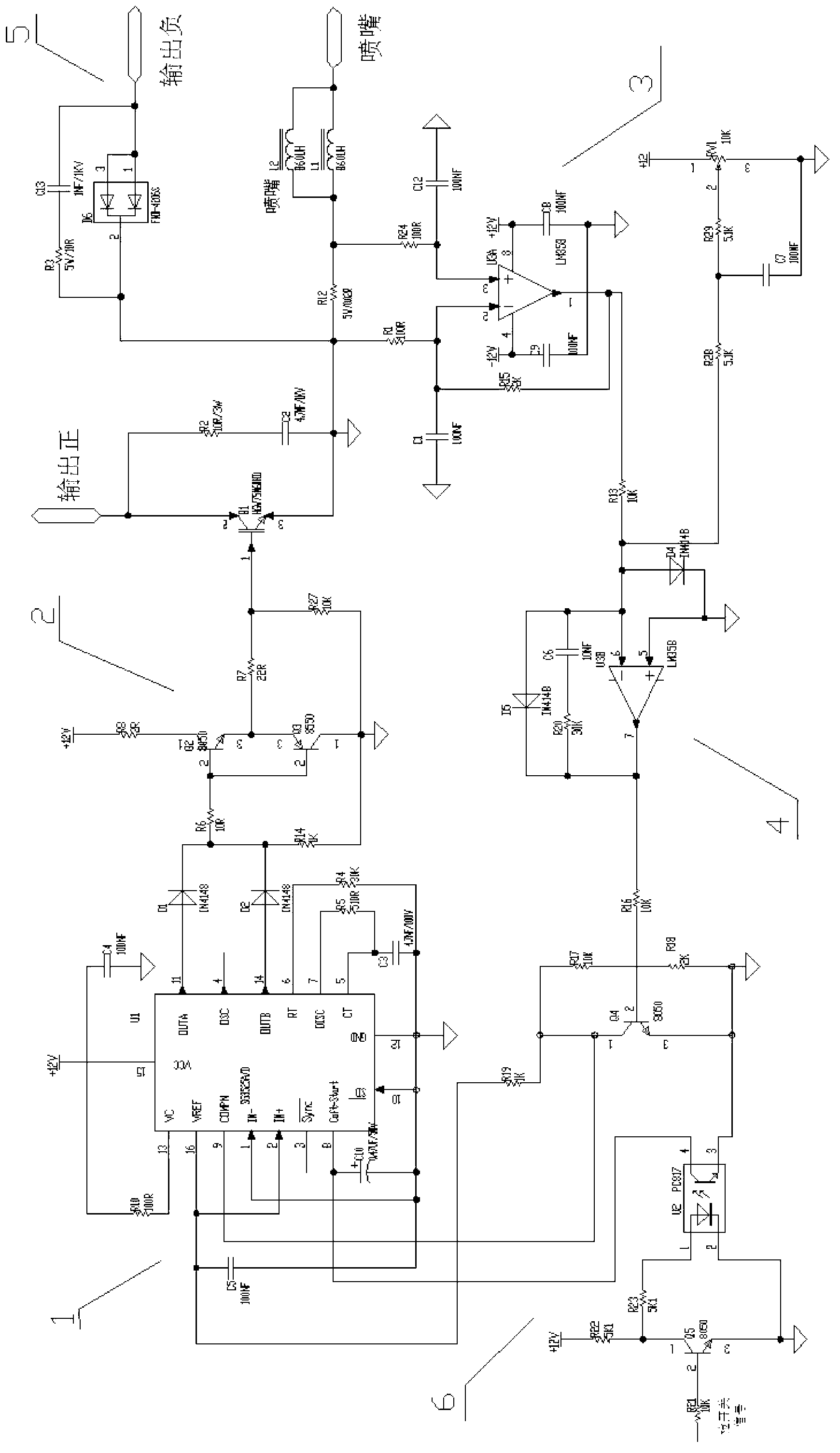
[0024] An arc-dimensioning chopper control circuit described in an embodiment of the present invention includes a power switch device drive circuit 1 for generating a pulse width regulation drive signal and limiting the current of the power switch tube under low power grid input conditions, and a drive circuit for controlling the current of the power switch tube. A differential amplification sampling circuit 2 for sampling and amplifying the current input by the low power grid, a current feedback loop control circuit 3 for adjusting the pulse width and adjusting the pulse width of the driving signal according to the amplified current signal, and a current feedback loop control circuit 3 for when the power switch is turned off When it is off and the output negative terminal is positive, t...