
Valve plate assembly

A valve plate and component technology, applied in the field of valve plate components, can solve the problems of poor wear resistance and inconvenient replacement of guide rails, and achieve the effects of improved wear resistance, good verticality, and convenient replacement and assembly

Inactive Publication Date: 2012-11-28
FORT VALE ENG SHANGHAI LTD
View PDF0 Cites 2 Cited by
  • Summary
  • Abstract
  • Description
  • Claims
  • Application Information

AI Technical Summary

Problems solved by technology

[0003] The technical problem to be solved by the present invention is to overcome the disadvantages of poor wear resistance and inconvenient replacement of the guide rail of the existing valve plate, and to provide a valve plate assembly that can make the guide rail of the valve plate more convenient to replace

Method used


Image

  • Valve plate assembly
  • Valve plate assembly
  • Valve plate assembly

Examples


Embodiment Construction

[0014] Hereinafter, preferred embodiments of the present invention are given in conjunction with the drawings to illustrate the technical solutions of the present invention in detail.

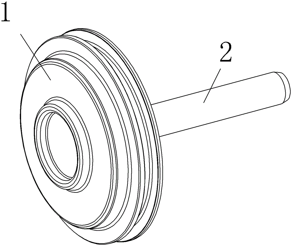
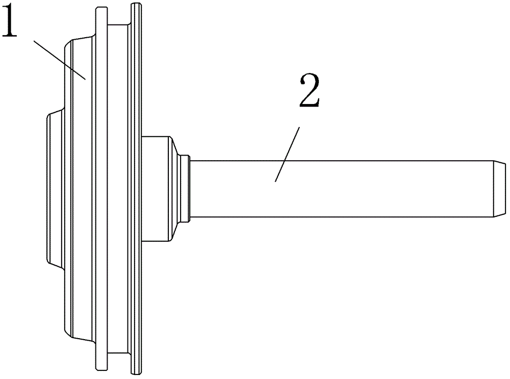
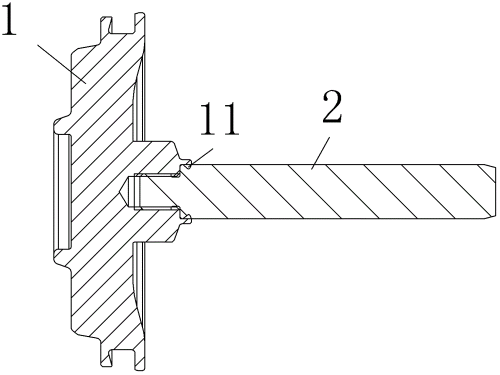
[0015] Such as Figure 1 to Figure 4 As shown, the valve plate 1 and the valve plate guide rail 2 are movably connected in a detachable manner. For example, threaded connection can be used. Specifically, an internal threaded hole for screw connection with the valve plate guide rail 2 can be drilled at the end of the valve plate guide rail 2, and an external thread corresponding to the internal threaded hole is processed on the peripheral surface of the valve plate guide rail.

[0016] In order to ensure the firmness of the connection between the valve plate 1 and the valve plate guide rail 2, a ring of inner rim 11 protruding inward is provided at the port of the internal threaded hole connecting the valve plate guide rail 2 and the valve plate 1. Correspondingly, a corresponding groove is provide...


PUM


Abstract

The invention discloses a valve plate assembly, which comprises a valve plate and a valve plate guide rail, wherein the valve plate is detachably movably connected with the valve plate guide rail. By the valve plate assembly, when the valve plate and the valve plate guide rail are assembled, the verticality is good, and the valve plate and the valve plate guide rail are in threaded connection, so the valve plate assembly is quickly and conveniently replaced or assembled.

Description

Technical field [0001] The invention relates to a valve assembly used on a mobile storage tank, in particular to a valve plate assembly. Background technique [0002] In the existing transportation of high-risk chemicals or highly toxic chemicals, dry coupling valves are often used to seal mobile storage tanks. With this dry coupling valve, the residue in the valve cavity will not leak after the valve is disconnected. Usually, when processing this kind of valve, the valve plate and the valve plate guideway are formed by forging from a whole piece of bar material. However, in use, it was found that because the valve plate guide rail and the valve plate are integrated in structure, on the one hand, the valve plate and the guide rail have different functions due to different functions, and the required material characteristics are different, and this integrated structure does not have the material changeability. On the other hand, the valve plate guide rail uses the same forging m...

Claims


Application Information

Patent Timeline
Patent Type & Authority Applications(China)
IPC IPC(8): B65D90/64
Inventor 赵云
Owner FORT VALE ENG SHANGHAI LTD
Learn More