Lifting drive mechanism of travelling crane

A technology of transmission mechanism and hoisting rope, applied in the direction of walking bridge cranes, cranes, transmission devices, etc., can solve the problems of high maintenance cost, large investment and complex structure, so as to reduce the initial investment, reduce the later use cost, extend the The effect of service life

Active Publication Date: 2012-11-28
常州市茂源科技有限公司
View PDF5 Cites 11 Cited by
  • Summary
  • Abstract
  • Description
  • Claims
  • Application Information

AI Technical Summary

Problems solved by technology

The above-mentioned utility model needs to install a mobile vehicle on the track of the main beam, the structure is more complicated, and the maintenance cost is higher
At present, the lifting transmission mechanism of the finished aerated concrete crane is gen

Method used


Image

  • Lifting drive mechanism of travelling crane
  • Lifting drive mechanism of travelling crane
  • Lifting drive mechanism of travelling crane

Examples


Example Embodiment

[0017] Example 1

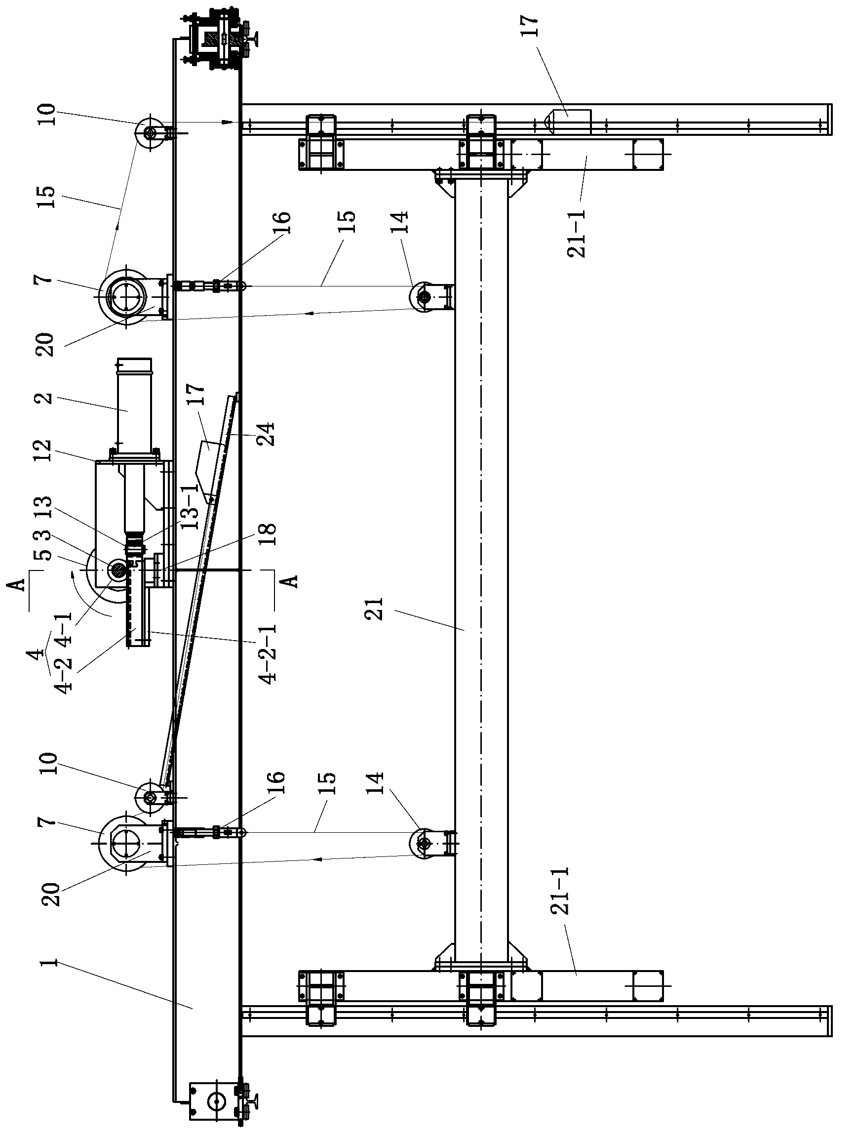
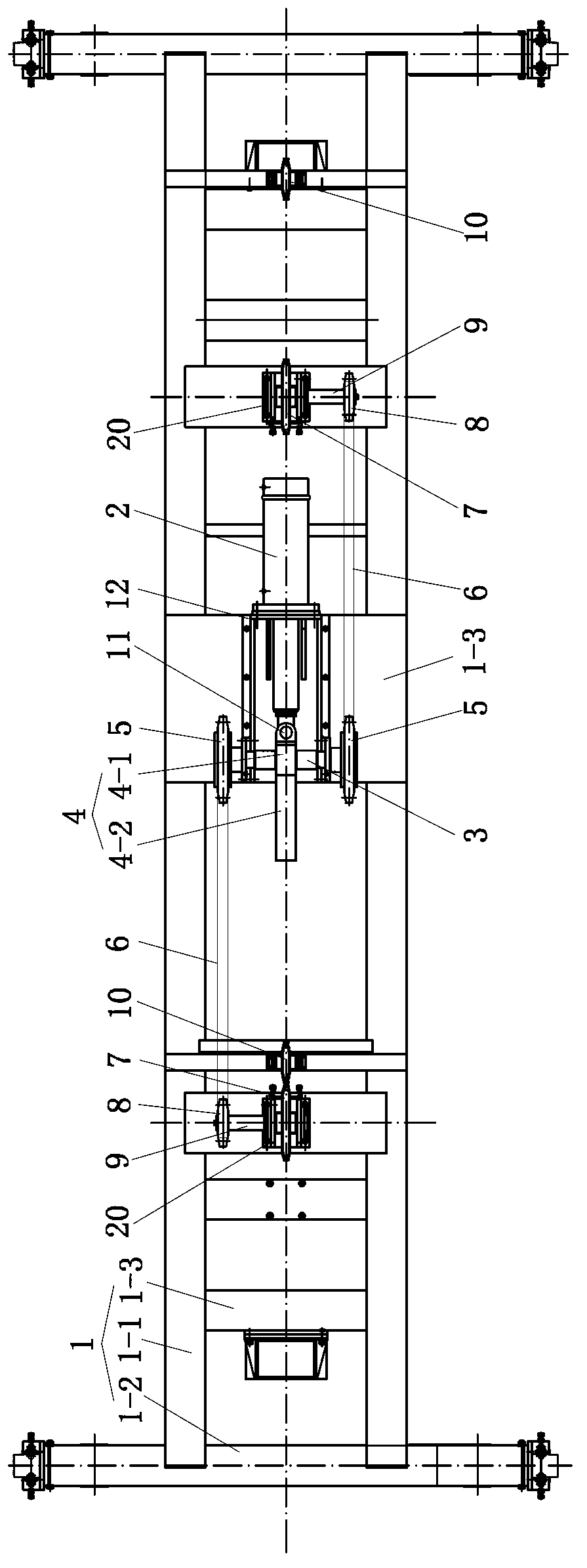
[0018] Embodiment 1 shown in the accompanying drawing comprises the hydraulic oil cylinder 2 that is arranged on the top surface of the main beam 1 and the lifting beam 21 below the main beam 1. In order to make the lifting beam 21 rise and fall stably, both sides of the lifting beam 21 are respectively fixed. There is a mobile support 21-1, and the mobile support 21-1 slides along the driving column. The main crane beam 1 has a frame composed of two beams 1-1 and beams 1-2 at both ends, and a support plate 1-3 or a support beam 1-3 is fixed on the frame corresponding to the mounting parts.

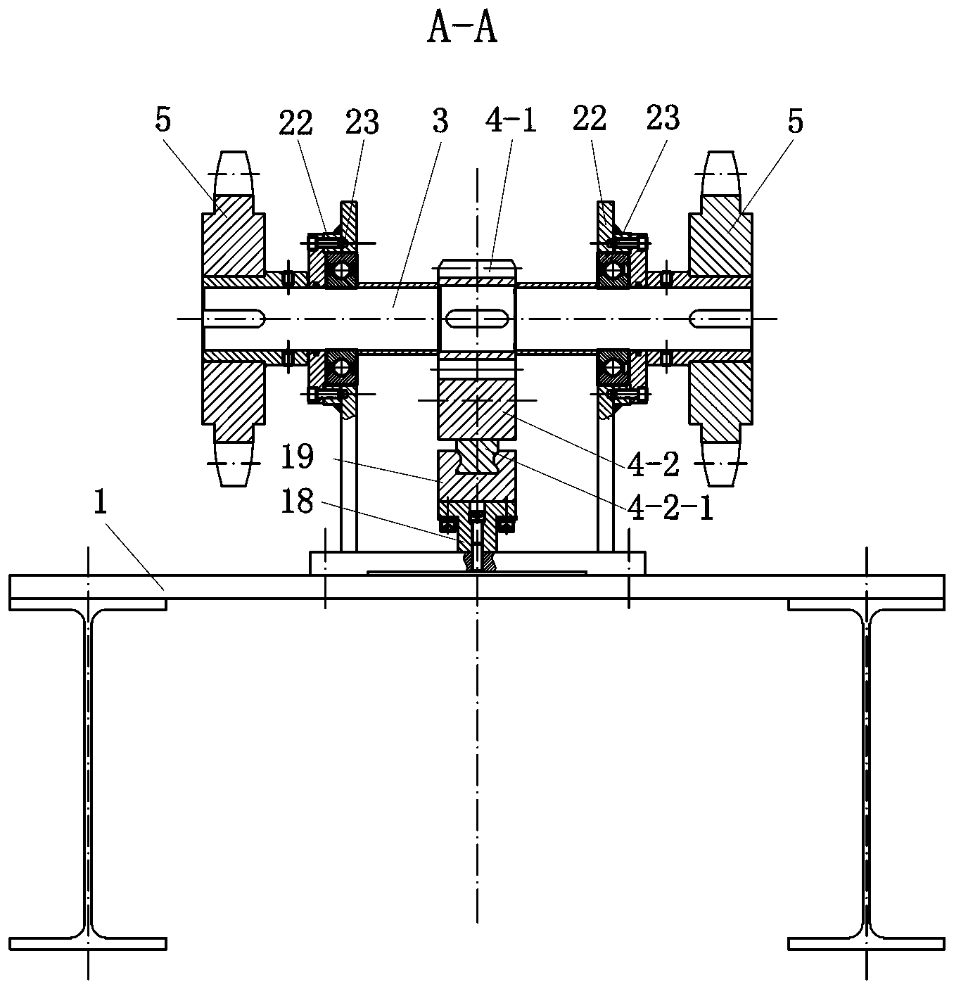
[0019] Drive shaft 3, driven shaft 9 on the left and right sides of drive shaft 3, and a rack and pinion pair 4 are arranged on the top surface of the main beam 1 for driving, and the rack 4-2 of the rack and pinion pair 4 is controlled by the hydraulic cylinder 2 Driven to slip, the gear 4-1 is installed on the drive shaft 3 to drive the drive shaft 3 to rotate. On t...


PUM


Abstract

The invention discloses a lifting drive mechanism of a travelling crane. The lifting drive mechanism of the travelling crane comprises a hydraulic oil cylinder and a lifting beam, wherein the top surface of a main beam of the travelling crane is provided with a drive shaft, a driven shaft located at left and right of the drive shaft and a gear rack pair; big chain wheels located at the front side and the back side of a gear are arranged on the drive shaft; the driven shaft is provided with small chain wheels corresponding to the big chain wheels and a lifting wheel; the big chain wheels and the small chain wheels are connected by chain rings; the top surface of the main beam of the travelling crane is provided with two first guide wheels respectively corresponding to two lifting wheels; two second guide wheels are arranged at the left and the right of the lifting beam; the main beam is connected with two lifting ropes to correspond to the two second guide wheels; each lifting rope passes through the second guide wheel, the lifting wheel and the first guide wheel all of which are at the same side; and the terminal of each lifting rope is connected with a balancing weight. Therefore, the maximum stroke of the hydraulic oil cylinder can be smaller than the maximum lifting distance, and the investment at the early stage and the use cost at the later stage of the hydraulic oil cylinder can be decreased. According to the force-saving principle of pulleys, the lifting drive mechanism of the travelling crane, disclosed by the invention, is good for protecting the hydraulic oil cylinder.

Description

technical field [0001] The invention relates to a transmission mechanism for driving and lifting. Background technique [0002] During the production of air-entrained concrete, it is often necessary to hoist the finished air-entrained concrete to the designated position by a special crane. The utility model with the Chinese patent number ZL 200420028850.4 (authorized announcement number CN 2693736Y) discloses a finished crane, which belongs to the finished crane for special equipment for aerated concrete. Two vertical rails are fixed vertically downward on the main beam, and two spreader arms run between the two vertical rails, and a fixture beam is fixed between the two spreader arms. A row of clamps are evenly distributed and fixed. The lifting and lowering of the fixture beam is fixed with a hydraulic cylinder in the middle of the main beam. The hydraulic cylinder pulls a mobile car running on the track of the main beam through a lifting rope. The main beam is fixed wit...

Claims


Application Information

Patent Timeline
IPC IPC(8): B66C17/04F16H47/02
Inventor 梁汉龙王仁祖
Owner 常州市茂源科技有限公司
Why Eureka
Try Eureka