Indoor humidifier

A technology for humidifiers and heating tubes, which is applied in air humidification systems, heating methods, lighting and heating equipment, etc. It can solve the problems of shortened service life and achieve the effects of reasonable structure, long service life and high work efficiency

Inactive Publication Date: 2012-11-28
任永平
View PDF0 Cites 6 Cited by
  • Summary
  • Abstract
  • Description
  • Claims
  • Application Information

AI Technical Summary

Problems solved by technology

When the humidity is sensed as high as the upper limit, the power is turned off, and when the humidity is sensed as low as the lower limit, the power is turned on again. Therefore, in order to maintain a certain humidity, the heater will be powered on and off frequently, resulting in a longer service life. shorten, so a new technical solution should be provided to solve the above problems

Method used


Image

  • Indoor humidifier

Examples


Embodiment Construction

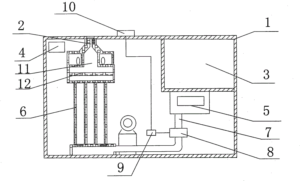
[0013] Such as figure 1 As shown, an indoor humidifier of the present invention includes a housing 1, a steam nozzle 2, a water tank 3 and a control panel 4 fixed on the housing 1, a water level controller 5 is fixedly installed on the lower part of the water tank 3, and the A heating tube 6 is fixed inside the housing 1, the heating tube 6 is electrically connected to the control panel 4, the water tank 3 is connected to the heating tube 6 through a pipeline 7, and the pipeline 7 connecting the water tank 3 and the heating tube 6 A water inlet valve 8 is arranged on it, and the water inlet valve 8 is connected with the MCU 9, and the MCU 9 is connected with the humidity sensor 10 arranged on the humidifier.

[0014] The heating tube 6 is a far-infrared heating tube, the upper end of which communicates with the buffer chamber 11 , and the water in the water tank 3 flows into the hollow cavity of the heating tube 6 through the pipeline 7 . A buffer plate 12 is arranged in the ...


PUM


Abstract

The invention discloses an indoor humidifier, which comprises a shell, a steam nozzle, a water tank and a control board which is fixed on the shell, wherein a water level controller is fixedly arranged on the lower part of the water tank; a heating pipe is fixed in the shell; the heating pipe is electrically connected with the control board; and the water tank is connected with the heating pipe through a pipeline. The indoor humidifier is characterized in that a water inlet valve is arranged on the pipeline for connecting the water tank and the heating pipe, the water inlet valve is connected with a micro control unit (MCU), and the MCU is connected with a humidity sensor arranged on the humidifier. The indoor humidifier has the advantages of reasonable structure, high working efficiency and long service life.

Description

technical field [0001] The invention relates to a humidifying device, in particular to an indoor humidifier. Background technique [0002] A humidifier is a device commonly used to improve indoor air quality. In an existing humidifier, a humidity sensor is connected to a power supply of a heater as a temperature control switch for the power supply. When the humidity is sensed as high as the upper limit, the power is turned off, and when the humidity is sensed as low as the lower limit, the power is turned on again. Therefore, in order to maintain a certain humidity, the heater will be powered on and off frequently, resulting in a longer service life. Therefore, a new technical solution should be provided to solve the above problems. Contents of the invention [0003] The object of the present invention is to provide an indoor humidifier with reasonable structure, high working efficiency and long service life in view of the above-mentioned deficiencies. [0004] In order ...

Claims


Application Information

Patent Timeline
Patent Type & Authority Applications(China)
IPC IPC(8): F24F6/14F24F11/02
Inventor 任永平
Owner 任永平
Why Eureka
Try Eureka