Magnet measuring device and magnet measuring method

A technology of measuring device and measuring method, which is applied in the direction of measuring device, measuring magnetic variables, the magnitude/direction of magnetic field, etc., can solve the problems of magnetic field attenuation, lack of processing of phase difference, deviation of measurement results, etc., and achieve the purpose of overcoming air gap instability or The effects of oversize, fast sampling and quality control, and improved consistency and accuracy

Active Publication Date: 2012-11-28
ADVANCED TECHNOLOGY & MATERIALS CO LTD
View PDF8 Cites 21 Cited by
  • Summary
  • Abstract
  • Description
  • Claims
  • Application Information

AI Technical Summary

Problems solved by technology

This measurement method has the following defects: 1. For the protection of the magnet and the Hall sensor, a certain gap must be reserved between the two, and the formed air gap causes the magnetic field to attenuate severely, so the measured data cannot be true Reflecting the magnetic field value at this point often requires some kind of compensation algorithm
2. The general-purpose Gauss meter probe is implanted with a Hall sensor and then sealed and cured in a small rod. Since the Hall sensor is extremely small, there is a certain deflection angle in the cured Hall sensor.
Since the magnetic field under the effective area is not uniform, there must be differences in the measured data
3. The lack of processing of the phase difference caused by the damping effect in the motion measurement, resulting in a small deviation in the measurement results
4. The current method and equipment are based on the measurement of a s

Method used


Image

  • Magnet measuring device and magnet measuring method
  • Magnet measuring device and magnet measuring method
  • Magnet measuring device and magnet measuring method

Examples


Embodiment Construction

[0048] Hereinafter, embodiments of the present invention will be described in detail with reference to the drawings.

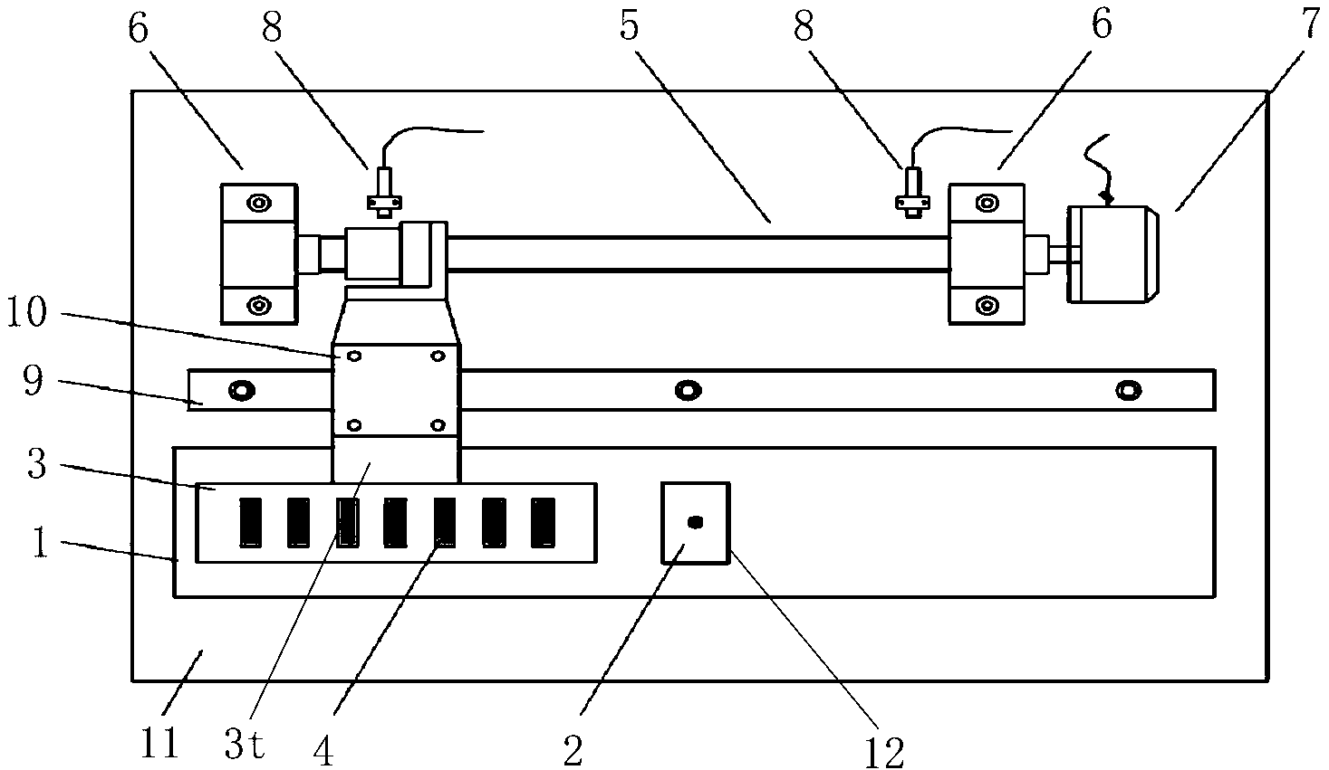
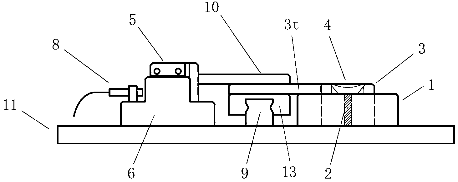
[0049] figure 1 is a top view of a neutral zone measuring device according to an embodiment of the present application; figure 2 It is a left view of the neutral zone measurement device according to the embodiment of the present application. like figure 1 , figure 2 As shown, the magnet neutral region measuring device proposed by the present invention includes: a lead screw 5, which has a screw and a nut; a motor 7, which is used to drive the screw in the lead screw 5 to rotate; a measuring platform 1, on which a probe is arranged Hole 12; Magnet positioning plate 3, wherein is provided with positioning hole 4, and positioning hole 4 is used for placing the magnet to be measured, and magnet positioning plate 3 moves on measuring platform 1 along with the movement of the nut of leading screw 5; Hall probe block 2. A Hall sensor is installed inside to meas...


PUM


Abstract

The invention discloses a magnet measuring device and a magnet measuring method. The magnet measuring device comprises a lead screw with a screw and nuts, a motor used to drive the screw in the lead screw to rotate, a measuring table which is provided with a probe hole, a magnet locating plate, and a Hall probe block. The magnet locating plate is provided with a location hole which is used to place a to-be-tested magnet, and the magnet locating plate moves on the measuring table with movement of the nuts of the lead screw. The Hall probe block is provided with a Hall sensor, and is used to measure magnetic fields of each position of the to-be-tested magnet, the to-be-tested magnet passing above the Hall sensor. The Hall probe block is disposed in the probe hole of the measuring table. The magnet measuring method uses forward and reverse measuring, numerical filter, and curve fitting. Using the magnet measuring device and the magnet measuring method can greatly improve efficiency. The device provided in the invention can make a surface of the magnet maintain contact with the sensor, and defects of inaccurate measuring results caused by an unstable air gap or an excessive air gap are overcome.

Description

technical field [0001] The invention relates to a measuring device and method, in particular to a device and a corresponding method for measuring the surface magnetic distribution and neutral zone width of a magnet. Background technique [0002] The surface magnetic distribution characteristics of multi-pole magnets are an extremely important parameter of magnet performance. Among them, the width and position of the neutral zone (also known as the transition zone) have a significant impact on the performance of each pole of the product: the positional deviation of the neutral zone will lead to The surface magnetic peaks of the adjacent magnetic poles of the magnet are asymmetric, and the deviation of the width of the neutral zone will lead to the deviation of the surface magnetic pole difference of the adjacent magnetic poles in the magnet. In actual production, the characteristics of the neutral zone have important guiding significance for product magnetization: when the po...

Claims


Application Information

Patent Timeline
IPC IPC(8): G01R33/02G01R33/10
Inventor 李俊峰刘涛杜世举刘德刘民
Owner ADVANCED TECHNOLOGY & MATERIALS CO LTD
Why Eureka
Try Eureka