Vehicular virtual terminal system based on dynamic map interface

A dynamic map and virtual terminal technology, applied in the field of vehicle virtual terminal systems, can solve the problems of wireless access technology heterogeneity and heterogeneous terminals, and achieve the effect of increasing user experience

Inactive Publication Date: 2012-11-28
NANJING UNIV
4 Cites 36 Cited by

AI-Extracted Technical Summary

Problems solved by technology

As well as the national major project "New Generation Broadband Wireless Mobile Communication Network", the above technical documents disclose that the current...

Abstract

The invention discloses a vehicular virtual terminal system based on a dynamic map interface. The vehicular virtual terminal system comprises a server, a mobile network and a terminal cluster, wherein the terminal cluster is used for communicating with the server through the mobile network; modules of the terminal cluster are used for obtaining a road section traffic flow and average vehicle speed data, uploading the information to the server through the mobile network and updating a dynamic map database through a dynamic map database management function module; and a portable communication module of a vehicular terminal unit is used for loading and displaying the dynamic map database information so as to realize a real-time map interface function, a route inducing function, a traveling track function, a field law-enforcement and evidence-obtainment function and an emergency treatment function. According to the vehicular virtual terminal system disclosed by the invention, a plurality of actual terminals are clustered into a virtual terminal according to service type, communication environment, terminal capability and user preference, specific details for service implementation are shielded for a vehicular terminal user, and the user is allowable to join the customization of service types, so that the vehicular virtual terminal system is suitable for the change of user environment and shields the difference between a network and a service platform for the user, therefore the user freely and seamlessly uses various types of new services.

Application Domain

Technology Topic

Emergency treatmentVirtual terminal +14

Image

  • Vehicular virtual terminal system based on dynamic map interface
  • Vehicular virtual terminal system based on dynamic map interface
  • Vehicular virtual terminal system based on dynamic map interface

Examples

  • Experimental program(1)

Example Embodiment

[0035] The operation mode of the vehicle-mounted virtual terminal system based on the dynamic map interface is described in detail below:
[0036] 1. Design concept and purpose of vehicle virtual terminal system based on dynamic map interface
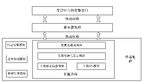
[0037] This system provides a customizable virtual terminal for different users of the vehicle network, so that the vehicle terminal can provide corresponding services according to the business type required by the user.
[0038] The in-vehicle virtual terminal provides four different services. They serve ordinary vehicles, dangerous goods vehicles, police vehicles and supervision vehicles respectively. The definitions and service contents of the four types of vehicles are as follows:
[0039] (1) Ordinary vehicles: including taxis, ambulances, private cars and other general vehicles; (2) Dangerous goods vehicles (such as muck trucks): vehicles for transporting dangerous goods or waste; (3) Police vehicles: law enforcement, forensics and Accident handling vehicles; (4) Supervision vehicles: vehicles for road maintenance, traffic incident supervision and handling.
[0040]The above four types of vehicles can be customized according to their respective needs and the functional modules provided by the corresponding virtual terminals, and the corresponding functions are as follows:
[0041] (1) Ordinary car: real-time map interface module, routing guidance module;
[0042] (2) Dangerous goods vehicle: driving tracking module;
[0043] (3) Police car: real-time map interface module, on-site law enforcement and evidence collection module;
[0044] (4) Supervision vehicle: real-time map interface module, emergency processing module;
[0045] 2. The structure of the vehicle virtual terminal system based on the dynamic map interface
[0046] like figure 1 and 9 As shown, the system includes a server, a mobile network, and a terminal cluster. The terminal cluster communicates with the server through the mobile network. The way that the server and the terminal cluster access the mobile network is CDMA, GSM, Wifi or Wimax. The terminal cluster includes a fixed camera module, a drive test sensor module, a vehicle terminal unit and an infrared detection module.
[0047] like figure 2 As shown, the vehicle-mounted terminal unit, the service object of the system, includes the following modules: vehicle-mounted mobile camera module, vehicle-mounted GPS module, portable communication module, vehicle-mounted processing and display module.
[0048] like image 3 As shown, the server includes a dynamic map database management function module, a real-time streaming video service function module, an optimal driving path analysis function module and an information release function module.
[0049] The various modules work together as Figure 10 As shown, the fixed camera module, road test sensor module, and infrared detection module can detect the average vehicle speed, traffic flow and other data of each road section in real time, and can also issue an alarm when abnormal conditions occur, and upload the information to the server and update the dynamic map through the mobile network. Database, the vehicle terminal unit obtains the map data from the server through the mobile network and displays it on the map interface, and obtains the alarm information. At the same time, the server obtains the optimal driving route according to the real-time traffic flow data and combined with the macro traffic flow prediction and transmits it wirelessly. Provide induction service to the vehicle terminal unit. The real-time streaming video captured by the vehicle-mounted terminal unit can be uploaded through the mobile network for other terminals, traffic control centers, and traffic police departments on demand.
[0050] 3. The specific implementation method of the vehicle virtual terminal system function based on the dynamic map interface
[0051] This system aggregates several heterogeneous actual terminals according to user requirements and business types to make different terminal clusters work together. The function implementation is described as follows:
[0052] (1) Real-time map interface function
[0053] like Figure 11 The generation process for the real-time map interface is described as follows:
[0054] like Figure 4 As shown, the fixed camera module, the road test sensor module and the infrared detection module obtain the traffic flow and average speed data of each road section. The fixed camera module is a module with a traffic incident detection function. It can measure the traffic flow, average vehicle speed and other parameters in a road section through real-time image processing technology. At the same time, in order to solve the problem of insufficient light at night, this system uses an infrared detection unit. Detect traffic incidents at night. The above modules will also issue alarm messages when abnormal events occur.
[0055] The traffic flow data such as average vehicle speed and traffic flow obtained by the above modules (that is, the fixed camera module, the road test sensor module and the infrared detection module) are uploaded to the server through the mobile network and the dynamic map database is updated, and the portable communication module of the vehicle terminal unit loads dynamic data. Map database information, the on-board processing and display module will display the real-time updated dynamic map interface. This system uses the average vehicle speed as the indicator of road congestion status. The lower the average vehicle speed, the more congested the road is, which is represented by different colors on the map interface. The difference of the average speed of each road section is displayed in red when the speed is greater than 100km/h, and displayed in green when the speed is less than 60km/h. Provide a basis, travel drivers can avoid congested areas, reduce the local load of the traffic system, improve the efficiency of traffic operation, and save travel time, while traffic managers can timely find congested areas and ease them.
[0056] The vehicle-mounted virtual terminal system based on the dynamic map interface provides users with dynamic maps that are updated in real time. Compared with the static images of traditional GIS, dynamic maps can display the time-varying information of road network traffic, such as: traffic control signals (traffic light changes), vehicles Changes in position and speed, and changes in the natural environment (rain, snow, and fog) are displayed in real time using image simulation images.
[0057] Fixed camera module, drive test sensor module and infrared detection module The specific methods of traffic incident detection are as follows: Figure 12 As shown, the system will first perform camera calibration, that is, the coordinates of the physical world correspond to the image coordinates, and then do background modeling, that is, the extraction of the image background, and model the image background, that is, static units such as roads and roadside fixed facilities. The separation of foreground and background provides necessary conditions, and then the difference method is used to differentiate the previous frame and the next frame to obtain the spatial position coordinates of the dynamic object and obtain the feature points of the dynamic object, so that the feature points of the front and rear frames are matched, and the system is dynamic. After the position coordinates of the object (this system is the vehicle) are measured, the vehicle speed in the actual coordinate system is calculated through coordinate transformation and the passing vehicles are counted (traffic flow is counted every 15 minutes). etc.) to do alarm processing, that is, to send abnormal event information.
[0058] For the technical realization of real-time road conditions, compared with static GIS, we use a layered method to update the background data of traffic road conditions to achieve dynamic real-time display. The system divides the dynamic map data into the following four layers:
[0059] (1) Static layer: static (semi-permanent) digital map database;
[0060] (2) Quasi-static layer: similar static information, not (yet) in the digital map database;
[0061] (3) Non-standard dynamic layer: temporary and dynamic information (such as weather, traffic conditions);
[0062] (4) Dynamic layer: dynamic and highly dynamic information about moving objects (vehicles, vulnerable road users and animals).
[0063] The four layers of data are superimposed and the specific road conditions are displayed through the GIS interface. The system is only interested in vehicle data, so the static and quasi-static layers are not updated. The dynamic map database of this system adopts SQLite provided by NAVTEQ company. The update and loading of the database adopts the function interface of SQLite in python language, and the map interface on the vehicle terminal adopts the API (application programming interface) provided by Google for map development.
[0064] (2) Routing induction function
[0065] like Figure 5 The shown system provides route guidance services for driving drivers. The server analyzes the function module based on the dynamic map database and the best driving path, and provides the best driving route from the current position to the destination in order to achieve the optimization of a certain indicator. Flexibly change routes according to changes in real-time traffic conditions. The portable communication module of the in-vehicle terminal unit obtains the optimal route through the mobile network and displays it on the map interface through the in-vehicle processing and display module. The dynamic optimal route can be obtained and displayed through real-time road condition analysis and traffic model prediction. Real-time variability, the optimal path will be updated in real time.
[0066] Taking into account the time-varying characteristics of traffic conditions and the fact that drivers only care about the overall congestion status of each road section rather than the specific driving status of each vehicle, the routing induction of this system is based on the macro-prediction model of traffic flow to provide drivers with dynamic information. The best path that takes into account the future evolution trend of road conditions.
[0067] (3) Emergency handling function
[0068] like Image 6 The shown fixed camera module, road test sensor module and infrared detection module provide an alarm function for traffic emergencies, such as speeding, traffic accidents, severe weather, infrastructure damage and other abnormal conditions, and transmit such signals through the mobile network Upload the server in time and feed back to the road monitoring department or the supervision vehicle. The portable communication module of the vehicle terminal unit gets the alarm signal, and then the vehicle processing and display module displays it to the terminal user of the supervision vehicle through the user interface. The user of the supervision vehicle and the traffic control center serve as traffic management The user can also issue instructions to deal with emergency situations on the user interface of emergency handling through the information release function module, dispatch human and material resources through the mobile network, and take emergency measures. The realization of traffic emergency perception here is the same as (1) real-time map interface function.
[0069] (4) On-site law enforcement and evidence collection functions
[0070] The process of video shooting, transmission and viewing at the accident scene is as follows: Figure 13 As shown, the video captured by the police car terminal is captured by the vehicle-mounted mobile camera module of the vehicle-mounted virtual terminal and transmitted by the portable communication module through the mobile network. The server accepts and initiates the conversation between the sender and the receiver for the law enforcement officers outside the scene to view, so that they can understand Important situations such as casualties, property losses, and emergency development trends provide a basis for scientific and rational decision-making, such as Figure 7 shown.
[0071] The mobile video of this system is collected by the vehicle-mounted mobile camera module of the vehicle-mounted terminal unit, and then processed by H.264 encoding and compression, and then sent to the server through RTP. Initiate an RTSP session between the sender and the receiver, and the real-time streaming video data at the receiver is received and played after being decoded by the VLC player software.
[0072] This system video coding adopts H.264 technology. H.264 is a video compression standard for IP environment, and its compression ratio is better than other video standards. It is divided into a video layer (VCL) and a network abstraction layer (NAL), where VCL focuses on the compression of video signals, and NAL defines the interface between the encoder and the transmission channel. This hierarchical processing structure enables H.264 to flexibly adapt to different transmission environments and improve transmission efficiency and QoS.
[0073] The twisted programming framework is adopted for the real-time streaming video service function module of the server and the RTSP session. Twisted is a server architecture implemented in python, a programming high-level language. The central concept of the framework is the idea of ​​non-blocking asynchrony.
[0074] Asynchronous network communication frameworks allow programs to be written to remain responsive while processing events without the use of threads. In this way, multiple tasks can be efficiently processed at the same time without introducing a complex threading mechanism. In the non-blocking asynchronous model, each task alternates, but it is still in a thread, and each task does not block. The multi-threading model will open up multiple threads to perform their own tasks.
[0075] In addition to being controlled by the program, multithreading is also controlled by the operating system, which can easily cause some unknown problems during the operation of the program. The asynchronous model is simpler than the multi-threaded model, because the running state of each task is controllable, and a task will continue to run until the task ends or is suspended. In this system, the server needs to respond to the on-demand applications of multiple clients at all times, which involves a large number of IO operations. The simple architecture model enables each task to run independently on the basis of ensuring the robustness of the system, and will not be affected by other tasks. Blocking greatly reduces the delay time of video streaming on demand and enhances the user experience.
[0076] The initialization and workflow of Twisted technology are as follows Figure 14 , first read the SPS (Sequence Parameter Set), PPS (Picture Parameter Set) and other information in its nalu (network abstract layer unit) structure, and generate an index suffixed with index according to the SDP protocol document. Open port 1556 of the server and always monitor the client's VOD application. When a client requests a video, the server first detects whether it has been parsed. After ensuring that the video in 264 format has been parsed, it uses the parsing information to establish an RTSP conversation with the client, and then transmits the video stream using the RTP protocol for the client to play.
[0077] (5) Driving tracking function
[0078] like Figure 8 As shown in the figure, this system provides the traffic control department with monitoring services for the driving routes of dangerous goods vehicles, such as: waste vehicles, muck trucks, etc., and displays their driving routes on the map. The GPS module and the vehicle-mounted mobile camera module are obtained and transmitted to the server by the portable communication module. The traffic manager can view the video of the vehicle-mounted mobile camera module through the mobile network to confirm whether the car is driving according to the command and whether it reaches the designated destination to prevent danger. The driver of the product car operates illegally, such as: not dumping garbage as required.
[0079] The realization of video shooting, transmission and viewing of this module is the same as that of the on-site law enforcement and evidence collection module.
[0080] 4. Virtual terminal classification service process
[0081] In-vehicle network users first customize the required business types, and then enter four different service interfaces after certification, namely: ordinary vehicles, dangerous goods vehicles, police vehicles and supervised vehicles, and then follow the required service procedures respectively. like Figure 15 In order to classify the service flow chart, the functional services provided by the system for four different types are:
[0082] Ordinary car: The virtual terminal service of ordinary cars first loads the map data, and displays the data on the map interface to provide users with the overall congestion situation of the road network. Combine real-time and predicted data to give the optimal driving route and display it.
[0083] Dangerous goods vehicle: The virtual terminal of the vehicle shoots and uploads the video taken along the way to the management and control center for viewing, and at the same time uploads the vehicle position data and driving route to the supervision department.
[0084] Police car: The police car shoots video evidence on the spot and uploads it to the traffic police department to provide a basis for its decision-making. The traffic police department can also issue law enforcement instructions to the police through virtual terminals.
[0085] Supervision vehicle: The supervision vehicle can get the alarm of the road network traffic emergency through the virtual terminal, issue emergency instructions, dispatch manpower and material resources to solve the problem.

PUM

no PUM

Description & Claims & Application Information

We can also present the details of the Description, Claims and Application information to help users get a comprehensive understanding of the technical details of the patent, such as background art, summary of invention, brief description of drawings, description of embodiments, and other original content. On the other hand, users can also determine the specific scope of protection of the technology through the list of claims; as well as understand the changes in the life cycle of the technology with the presentation of the patent timeline. Login to view more.

Similar technology patents

Orphaned utterance detection system and method

InactiveUS20160055240A1High precisionImprove user experienceNatural language translationWeb data indexingLanguage understandingDialog system
Owner:MICROSOFT TECH LICENSING LLC

Classification and recommendation of technical efficacy words

Why Eureka
Try Eureka