Crown spring jack contacting piece
A socket contact and crown spring technology, which is applied in the field of high reliability crown spring socket contacts, can solve the problems of easy detachment, axial and radial serial movement of crown spring contact rings, etc., and achieve reliable contact and simple structure , The effect of small insertion force
- Summary
- Abstract
- Description
- Claims
- Application Information
AI Technical Summary
Problems solved by technology
Method used
Image
Examples
Embodiment 1
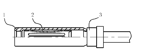
[0017] Embodiment 1 (single head crown spring type contact ring formal installation) as figure 2 As shown, the crown spring socket contact includes a pressure ring 4 with a central hole, a crown spring contact ring 2 and a tubular socket 1, and the crown spring contact ring 2 is installed in the inner hole of the tubular socket 1, The front end of the inner hole of the tubular jack 1 is provided with a flaring section, and its aperture is larger than the straight hole section at the rear end. There is a tapered hole transition section between the flaring section and the adjacent straight hole section. A pressure ring 4 is installed in the hole section, and the pressure ring 4 has a central hole for the insertion pin to pass through. The tail end of the pressure ring 4 cooperates with the inner hole expansion section of the tubular jack 1. One end of the spring type contact ring 2 is provided with U-shaped grooves and contact strips evenly distributed on the circumference. Be...
Embodiment 2
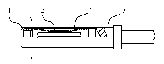
[0018] Embodiment 2 (single head crown spring type contact ring reverse installation) such as Figure 4 As shown, the contact piece includes a tubular socket 1, a crown spring contact ring 2 and a pin 3, the crown spring contact ring 2 is placed in the inner hole of the tubular socket 1, and one end of the crown spring contact ring 2 is provided with U-shaped grooves and contact strips evenly distributed on the circumference, the arc transition at the root of the U-shaped grooves can avoid stress concentration. Between the straight hole section of the inner hole of the hole 1 and the mating surface of the front end of the pin 3, the other end gap is assembled in the straight hole of the tubular jack 1. In this contact piece, one end of the crown spring contact ring is crimped between the tail end of the tubular jack and the front end of the pin, and the interference fit between the tubular jack and the pin ensures that the contact strip of the crown spring contact ring is pres...
Embodiment 3
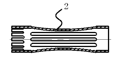
[0019] Embodiment 3 (double-ended crown spring type contact ring) such as Figure 5 As shown, the crown spring socket contact includes a pressure ring 4 with a central hole, a crown spring contact ring 2 and a tubular socket 1, and the crown spring contact ring 2 is installed in the inner hole of the tubular socket 1, Slots and contact strips are evenly arranged around the two ends of the crown spring contact ring 2, and the inner hole of the tubular jack 2 is provided with a mating surface with the pressure ring 4 and the pin 3, and the contact between the two ends of the crown spring contact ring 2 The strips are placed between the corresponding mating surfaces, and the two ends of the crown spring type contact ring are fixed through the matching connection of the tubular jack, the pressure ring and the pin.
[0020] In this contact piece, one end of the crown spring type contact ring is crimped on the tail end of the pressure ring and the front end of the tubular socket, th...
PUM
 Abstract
Description
Claims
Application Information
 - R&D
- Intellectual Property
- Life Sciences
- Materials
- Tech Scout
- Unparalleled Data Quality
- Higher Quality Content
- 60% Fewer Hallucinations
Browse by: Latest US Patents, China's latest patents, Technical Efficacy Thesaurus, Application Domain, Technology Topic, Popular Technical Reports.
© 2025 PatSnap. All rights reserved.Legal|Privacy policy|Modern Slavery Act Transparency Statement|Sitemap|About US| Contact US: help@patsnap.com


