Electric blower and electric cleaner using same
A blower and motor technology, applied in the fields of electric vacuum cleaners and electric blowers, can solve problems such as narrowing of the flow path area, deviation of the direction of the rotating shaft, and reduction of air supply efficiency
- Summary
- Abstract
- Description
- Claims
- Application Information
AI Technical Summary
Problems solved by technology
Method used
Image

Examples
Embodiment approach 1
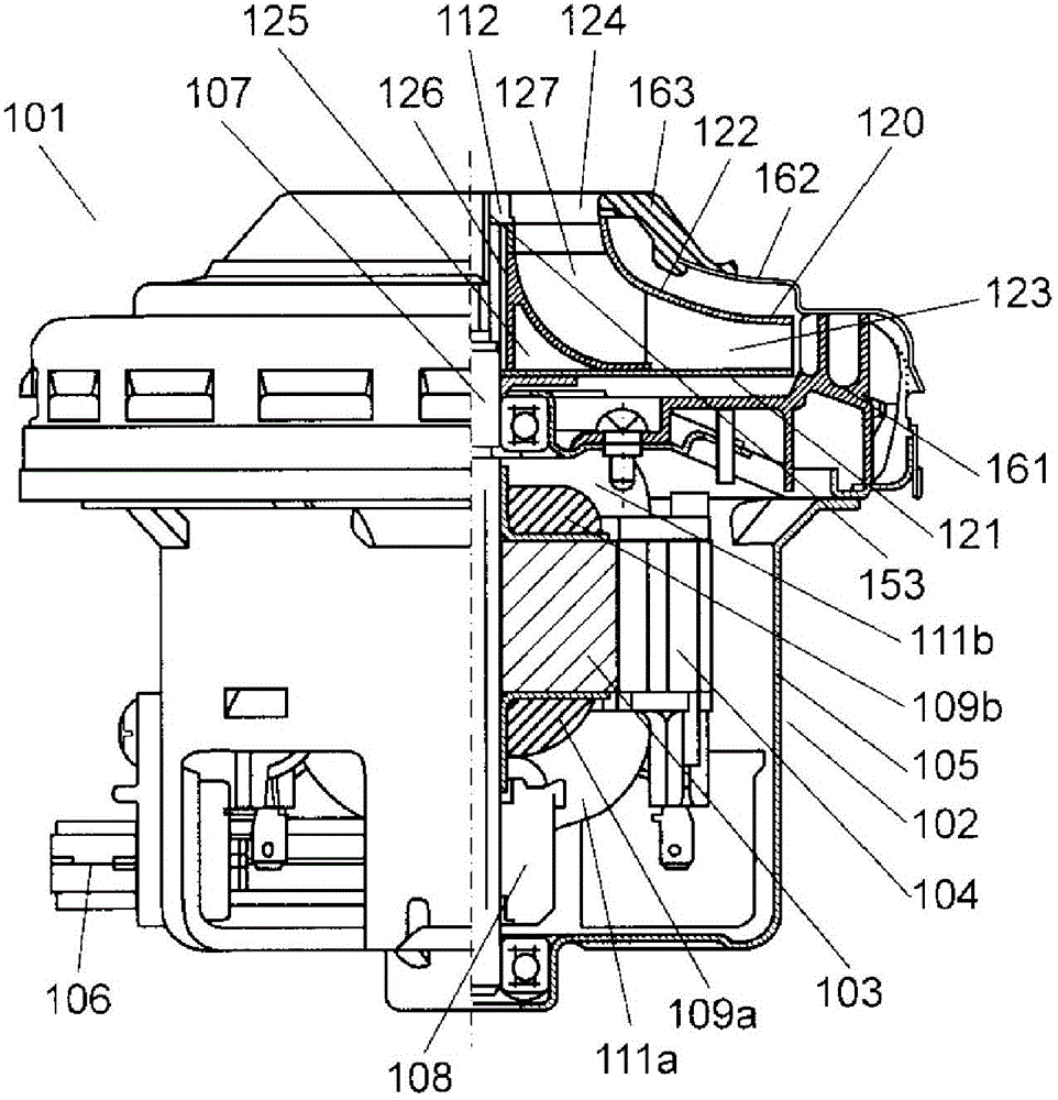
[0044] figure 1 It is a partial side sectional view of the electric blower according to Embodiment 1 of the present invention. A motor 102 is arranged in the electric blower 101 . The motor 102 is a type of motor called a brushed motor, and is composed of a rotor portion 103 , a stator portion 104 , a bracket 105 covering them, and a brush portion 106 . The brush portion 106 is provided on the lower side of the rotor portion 103 and the stator portion 104 . The rotor part 103 is provided with a rotating shaft 107, a commutator part 108, and coil parts 109a and 109b. Coil portions 111 a and 111 b are also provided on the stator portion 104 . Furthermore, the impeller 120 is connected to the rotating shaft 107 through a nut 112 . That is, the impeller 120 is driven to rotate by the motor 102 .
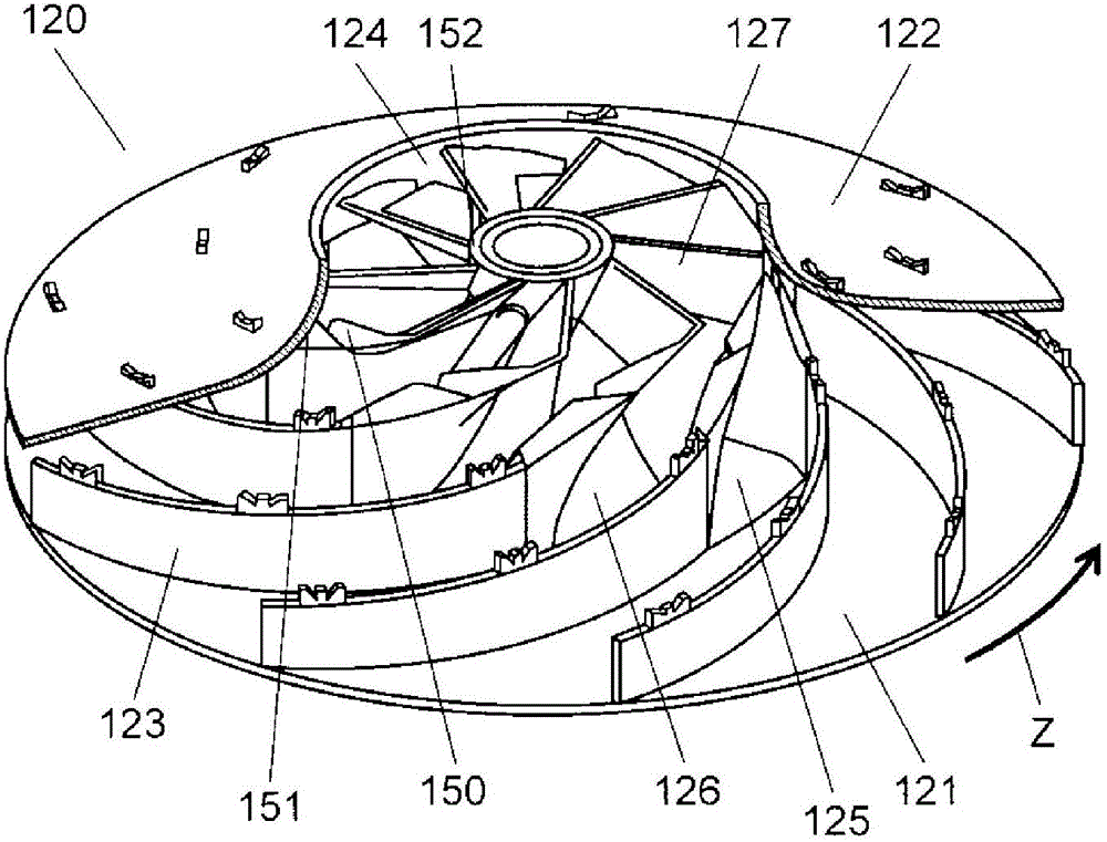
[0045] figure 2 It is a partial cross-sectional view of the impeller of the electric blower according to Embodiment 1 of the present invention. The impeller 120 is composed of a...
Embodiment approach 2
[0073] Figure 8 It is a perspective view of a wind deflector of an electric blower according to Embodiment 2 of the present invention, Figure 9 It is a rear perspective view of the first wind deflector of the electric blower. Only points different from Embodiment 1 will be described in Embodiment 2 of the present invention.
[0074] Embodiment 2 of the present invention differs from Embodiment 1 in the following points. On the mating surface 203a of the first wing portion 202a of the first wind deflector 201a, a stepped third step portion 204a is provided as an engaging portion. In addition, a stepped fourth step portion 204b is provided on the mating surface 203b of the second wing portion 202b of the second wind deflector 201b, and the fourth step portion 204b has a Figure 7 The first protrusion 145 is shown. The fourth stepped portion 204b is engaged with the third stepped portion 204a.
[0075] In addition, a stepped fifth step portion 205b having a second protrusi...
Embodiment approach 3
[0078] Figure 10 It is a perspective view of a wind deflector of an electric blower according to Embodiment 3 of the present invention, Figure 11 It is a rear perspective view of the first wind deflector of the electric blower. In Embodiment 3, only points different from Embodiment 1 will be described.
[0079] Embodiment 3 of the present invention differs from Embodiment 1 in the following points. The first wing portion 302a of the first wind deflector 301a and the second wing portion 302b of the second wind deflector 301b respectively have mating surfaces 303a, 303b. In addition, a third convex portion 305 and a fourth convex portion 308 are provided on the mating surface 303b. The third convex portion 305 is provided on the negative pressure surface 304 side on the outer peripheral side of the second wing portion 302b. In addition, the fourth convex portion 308 is provided on the pressure surface 307 side on the inner peripheral side of the second wing portion 302b. ...
PUM
 Abstract
Description
Claims
Application Information
 - R&D
- Intellectual Property
- Life Sciences
- Materials
- Tech Scout
- Unparalleled Data Quality
- Higher Quality Content
- 60% Fewer Hallucinations
Browse by: Latest US Patents, China's latest patents, Technical Efficacy Thesaurus, Application Domain, Technology Topic, Popular Technical Reports.
© 2025 PatSnap. All rights reserved.Legal|Privacy policy|Modern Slavery Act Transparency Statement|Sitemap|About US| Contact US: help@patsnap.com