
Electrowetting display device

An electrowetting display and electrowetting technology, which is applied in the directions of instruments, light guides, optics, etc., can solve the problems of unsatisfactory quality of display devices.

Active Publication Date: 2012-11-28
LIQUAVISTA BV
View PDF6 Cites 22 Cited by
  • Summary
  • Abstract
  • Description
  • Claims
  • Application Information

AI Technical Summary

Problems solved by technology

However, the quality of display devices made using this method is not satisfactory

Method used


Image

  • Electrowetting display device
  • Electrowetting display device
  • Electrowetting display device

Examples


Embodiment Construction

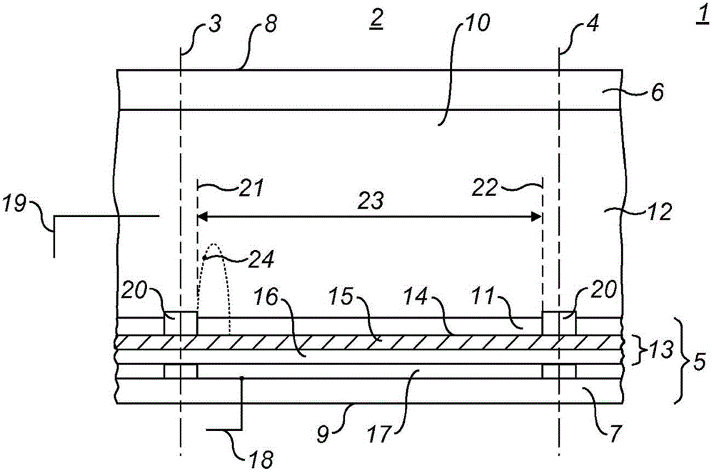
[0028] figure 1 A diagrammatic cross-section of part of an electrowetting device is shown in the form of an electrowetting display device 1 . The display device comprises a plurality of picture elements 2, one of which is shown in the figure. The lateral extent of a cell is indicated by two dashed lines 3, 4 in the figure. The pixel includes a first support plate 5 and a second support plate 6 . These support plates may be separate components of each cell, but preferably they are shared by multiple cells. The support plate may comprise glass or polymer substrates 6, 7 and may be rigid or flexible.

[0029] The display device has a viewing face 8 and a rear face 9 on which images or displays formed by the display device can be viewed. In the figure, the first support plate 5 faces the back 9; the second support plate 6 faces the viewing surface; alternatively, the first support plate can face the viewing surface. Display devices may be reflective, transmissive, or transfle...


PUM


Abstract

The present invention relates to a method for making a support plate for an electrowetting device. The method comprises the steps of: providing the support plate with a hydrophobic layer; arranging a pattern of hydrophilic material on the hydrophobic layer; and removing a surface layer of the hydrophobic layer by a solvent. The present invention further relates to an electrowetting device including a support plate that comprises a hydrophobic layer having a thickness, and a pattern of hydrophilic material arranged on a first area of the hydrophobic layer, the thickness of the hydrophobic layer being larger within the first area than outside the first area.

Description

technical field [0001] The present invention relates to an electrowetting display device and a method for manufacturing the electrowetting display device. Background technique [0002] An electrowetting display device such as that described by Zhou et al. in J. Micromech. Microeng. 19 (2009) 065029 comprises two support plates, each comprising a substrate. A pattern of walls is arranged on a support plate, the pattern defining the extent of a picture element of the display device. The area between the walls of the picture elements (also known as pixels) is called the display area, on which the display effect occurs. Display effects are produced by the motion of two immiscible fluids (oil and electrolyte) within a pixel under the influence of an electric field. When no field is applied, the oil forms a layer covering the display area of ​​the support plate. When the field is applied, the oil contracts and the electrolyte abuts the majority of the support plate. If for exa...

Claims


Application Information

Patent Timeline
Patent Type & Authority Applications(China)
IPC IPC(8): G02B26/02
CPCG02B26/005G02B26/004G02B26/026G02F1/17G02B6/44384
Inventor 罗马里克·马萨德基亚拉·科姆蒂博克·约翰内斯·芬斯特拉
Owner LIQUAVISTA BV
Learn More