
a muffler

A technology for mufflers and appliances, applied in mufflers, machines/engines, engine components, etc., can solve the problems of increased back pressure, too fast jet flow rate, and too strong reflected wave intensity, so as to reduce back pressure and eliminate narrow-band noise. , Solve the effect of airflow reflux

Active Publication Date: 2016-03-23
AUTOMOBILE RES INST OF TSINGHUA UNIV IN SUZHOU XIANGCHENG
View PDF6 Cites 2 Cited by
  • Summary
  • Abstract
  • Description
  • Claims
  • Application Information

AI Technical Summary

Problems solved by technology

But when it comes to the back pressure problem, the intubation tube of this structure is not a good design, the reasons are as follows: 1. Gas backflow problem: For the gas outlet of the air intake intubation tube, the air flow velocity is high, and the pressure in the tube may Higher than the pressure outside the tube, at this time, the airflow will flow from the outside of the tube through the small hole on the intake tube into the intake tube, forming a reverse flow, making the flow unsmooth and resulting in an increase in back pressure; 2 2. The problem of too fast flow velocity of the jet: when the air flow is ejected from the gas outlet of the intake tube, due to the large difference between the parameters of the jet and the fluid outside the tube, the loss of macroscopic flow kinetic energy is large, and the impact of the jet on the second end cap will also cause The kinetic energy of the macroscopic flow is lost, resulting in an increase in back pressure; 3. The problem of too strong reflected wave intensity: the airflow is ejected from the gas outlet of the intake tube and hits the second end cover, and the gas inserted into the intake tube A high-pressure area is formed at the front end of the outlet, and a reflected wave is formed, and the reflected wave acts on the airflow in the intake tube, resulting in an increase in back pressure
Considering comprehensively, when the muffler with this kind of inner tube structure obtains good noise reduction performance, the back pressure will usually increase, which will affect the power performance of the engine.

Method used


Image

  • a muffler
  • a muffler
  • a muffler

Examples


Embodiment Construction

[0021] The present invention will be further described below through a muffler with a specific structure and in conjunction with the accompanying drawings.

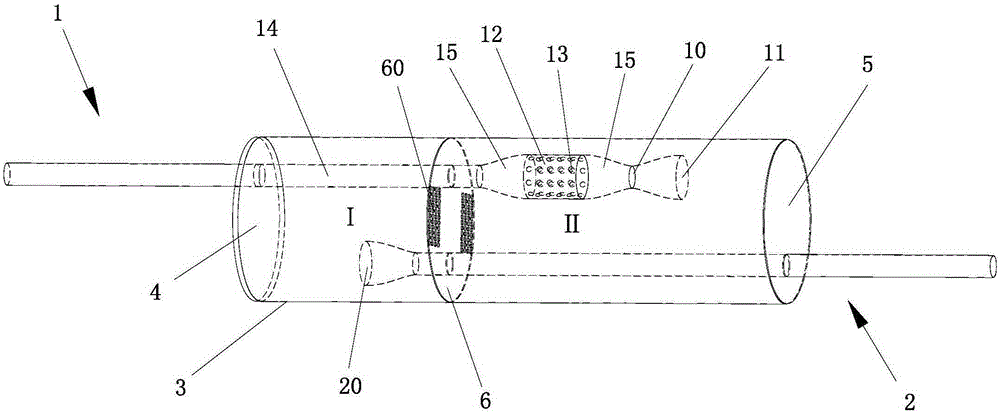
[0022] Such as Figure 2~3 As shown, a muffler includes an inner insertion pipe structure, a cylinder body 3, a first end cap 4 and a second end cap 5 fixedly arranged at both ends of the cylinder body 3, and the first end cap 4 and the second end cap 5 are all connected to the The cylinder 3 is sealed and connected, and a partition 6 is fixed in the cylinder 3 along the direction perpendicular to the axial direction of the cylinder 3. The partition 6 divides the cylinder 3 into a first chamber I and a second chamber II. A plurality of evenly distributed through-holes 60 are opened on 6, and the through-holes 60 communicate the first chamber I and the second chamber II.

[0023] The inner cannula structure includes an air intake inner cannula 1 and an air outlet inner cannula 2, and the air intake inner cannula 1 include...


PUM


Abstract

The invention relates to a muffler, which has an inner inserted pipe structure. The inner inserted pipe structure comprises an air inlet inner inserted pipe and an air outlet inner inserted pipe, wherein the air inlet inner inserted pipe comprises a first pipe section, a second pipe section and a middle pipe section between the first and second pipe sections; transition pipe sections are connected to the two ends of the middle pipe section, and are connected with the first and second pipe sections respectively; the diameters of the first and second pipe sections are smaller than that of the middle pipe section; a plurality of penetration holes are uniformly formed in the wall of the middle pipe section along the circumferential direction of the middle pipe section. The muffler has excellent overall characteristics of muffling and back pressure, and the problem of excessively high back pressure of a conventional muffler with an excellent muffling characteristic is solved.

Description

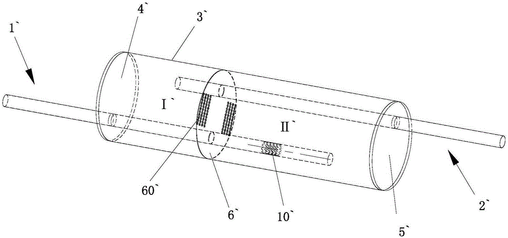
technical field [0001] The invention mainly relates to a muffler, which is applied to exhaust systems of internal combustion engines such as automobiles. Background technique [0002] There are two main research objectives for the exhaust system of internal combustion engines: 1. To reduce the back pressure of the muffler as much as possible so that the engine can obtain good dynamic performance; 2. To reduce the exhaust noise as much as possible to reduce noise pollution. However, the existing mufflers cannot meet the requirements of these two aspects at the same time, such as figure 1 Shown is the embodiment diagram of the muffler in the prior art. As shown in the figure, the muffler in the prior art includes an inner tube structure, a cylinder body 3', a first end cap 4' and a second end cap 5' fixedly arranged at both ends of the cylinder body 3', and inside the cylinder body 3' A partition 6' is fixedly installed, and the partition 6' divides the cylinder body 3' into...

Claims


Application Information

Patent Timeline
Patent Type & Authority Patents(China)
IPC IPC(8): F01N13/00
Inventor 郑四发张琦吴熙平
Owner AUTOMOBILE RES INST OF TSINGHUA UNIV IN SUZHOU XIANGCHENG
Learn More