
Valve

A valve body and valve housing technology, used in flow control, non-electric variable control, instruments, etc., can solve the problems of shower head deformation, easy sealing, shower head breakage, etc., to save space, resist functional failure and damage. Effect

Active Publication Date: 2012-11-28
NEOPERL
View PDF7 Cites 0 Cited by
  • Summary
  • Abstract
  • Description
  • Claims
  • Application Information

AI Technical Summary

Problems solved by technology

The disadvantage, however, is that these shower openings, which are relatively small in terms of their net cross-section, can easily close due to calcium and dirt deposits
As the shower opening becomes more and more closed, there is an increased risk that the water flowing through the shower head will build up pressure there, which can lead to deformation of the shower head and eventually to a breakage of the shower head

Method used


Image

  • Valve
  • Valve
  • Valve

Examples


Embodiment Construction

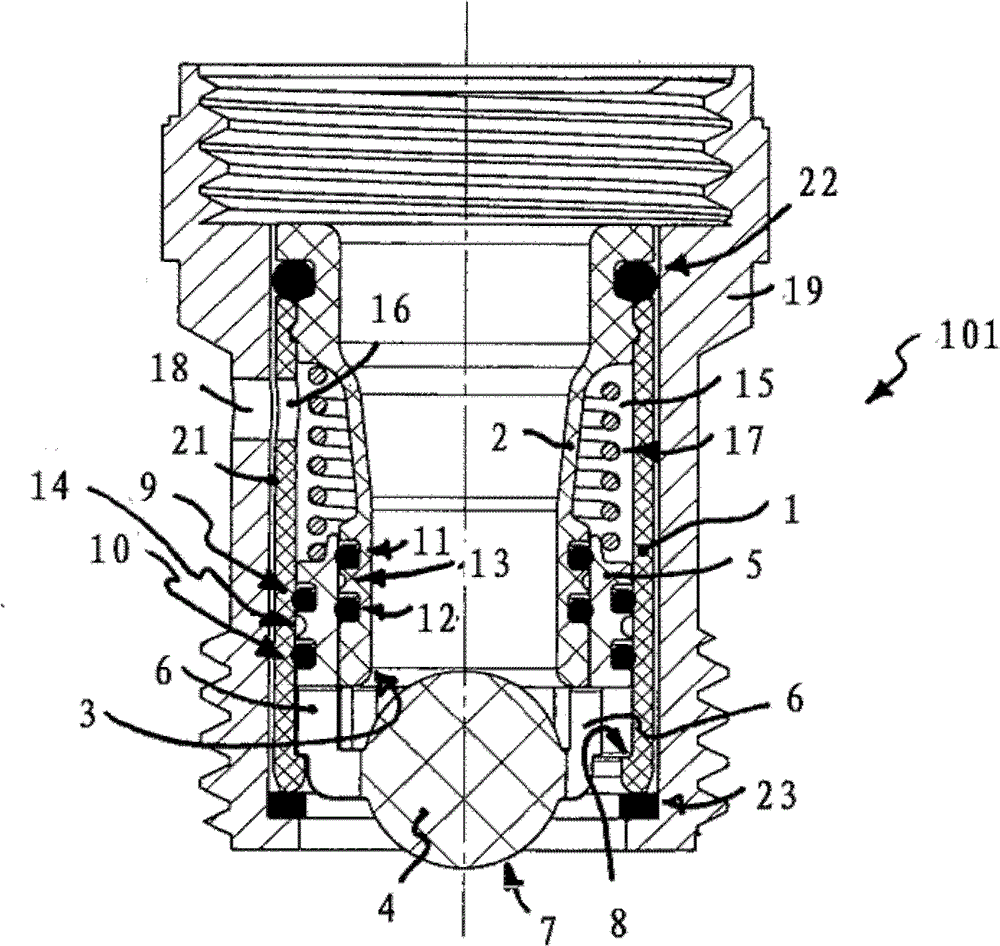
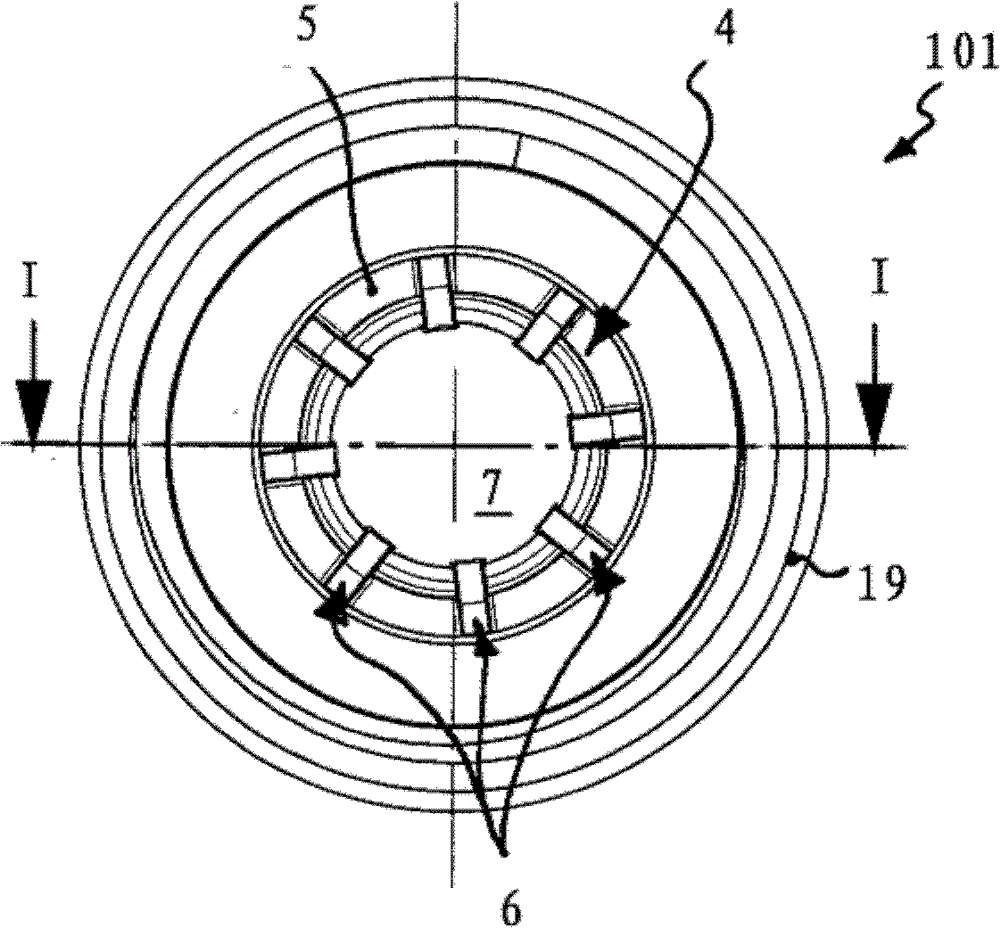
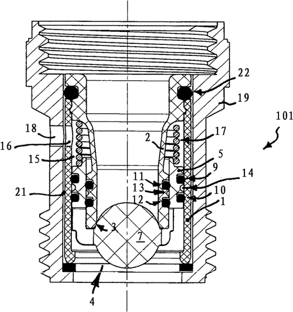
[0043] exist Figures 1 to 18 Different embodiments 101, 105 and 113 and 117 of valves are shown in , which can be used as pressure limiters and which, in the exemplary embodiment shown here, can be installed in sanitary water mains. Each of the valve embodiments 101, 105, 113 and 117 shown here has a valve housing 1, in the housing interior of which a flow guide 2 is arranged, the outflow side of which The peripheral region of forms the valve seat 3 for the valve body 4 . The valve body 4 is able to switch between the open position and the closed position by the pressure acting on the valve body 4 of the fluid flowing in and through the flow guide 2 on the one hand and by the counterpressure acting on the valve body 4 against the normal flow direction on the other hand. movement between positions.

[0044] Valve implementation forms 101, 105 and 113 and 117 are in figure 1 , 2 , 5, 6, 9, 10, 13, 17 and 18 are shown in the open position of the valve, while these valve impl...


PUM


Abstract

The invention relates to a valve (101) that can be used as a pressure limiter, for example in a sanitary supply line. The valve (101) according to the invention comprises a valve housing (1), a fluid line piece (2) being provided in the housing interior thereof, the downstream side circumferential edge area thereof forming a valve seat (3) for a valve body (4), wherein said valve body (4) can be displaced between an open position and a closed position, in which closed position the valve body (4) acts on the downstream circumferential edge area of the fluid line piece (2), by the pressure of the fluid flowing in through the fluid line piece (2) on one side, and a downstream side pressure acting on the valve body (4) opposite to the regular flow-through direction on the other side.

Description

technical field [0001] The invention relates to a valve which is intended in particular for hygienic use. Background technique [0002] The operation of pressure-sensitive and in particular pressure-free hot water generators often requires special taps which do not provide too much resistance to the water flowing through the supply line and thus avoid an undesired pressure increase. For example, generally only non-aerated / non-foaming jet regulators and thus such hot water outflows which do not generate counterpressure can be used in combination with pressure-sensitive water generators. [0003] Hygienic shower heads of this type are increasingly gaining attention, which have a shower head with a large shower surface with a plurality of relatively small shower openings. With such a shower head, a shower shower formed by a plurality of fine, thread-like individual jets can be produced. A disadvantage, however, is that these shower openings, which are relatively small in term...

Claims


Application Information

Patent Timeline
Patent Type & Authority Applications(China)
IPC IPC(8): G05D7/01
CPCG05D7/016Y10T137/7668Y10T137/7852Y10T137/7853Y10T137/7923Y10T137/7924Y10T137/7928
Inventor M・范迈尔
Owner NEOPERL
Learn More