Lifting mechanism of coating machine

A lifting mechanism and coating machine technology, which is applied in the field of coating machines, can solve problems such as easy residual coating lubricating fluid, easy tilting, and affecting product quality

Inactive Publication Date: 2012-12-05
昆山艾博机器人股份有限公司
View PDF4 Cites 13 Cited by
  • Summary
  • Abstract
  • Description
  • Claims
  • Application Information

AI Technical Summary

Problems solved by technology

[0004] In order to solve the problem that the structure of the lifting mechanism of the coating machine in the prior art is relatively complicated, it is easy to tilt during the transportation of the product, and at the same time, after the coating is completed, the coating lubricating fluid is easy to remain on the product, and after drying, it is very easy to affect the product quality. , the present invention provides a coating machine lifting mechanism that is simple in structure, easy to use, and can quickly, accurately and stably lift products

Method used


Image

  • Lifting mechanism of coating machine
  • Lifting mechanism of coating machine

Examples


Embodiment Construction

[0014] The present invention will be further described below in conjunction with the accompanying drawings.

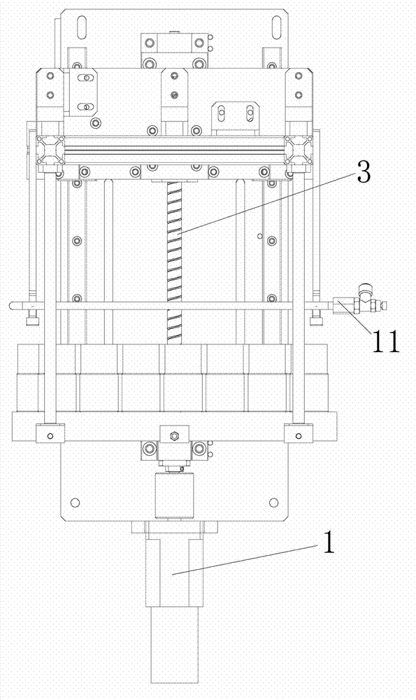
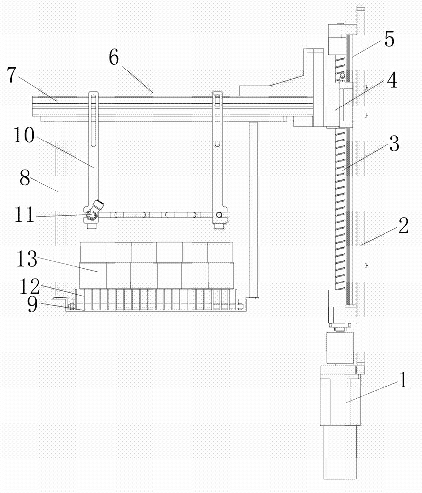
[0015] Such as Figure 1-2 As shown, a coating machine lifting mechanism includes a motor 1, a base plate 2, a lead screw 3, a sliding plate 4, a guide rail 5 and a placement frame 6. The front end middle part of the base plate 2 is provided with a lead screw 3. The side is provided with a guide rail 5, the bottom of the screw 3 is connected with the motor 1, the middle part of the rear end of the sliding plate 5 is provided with a sliding block that cooperates with the lead screw 3, and the two sides of the sliding block are respectively provided with corresponding side guide rails 5. The chute is connected with a shelf 6 for placing products at the front end of the slide plate 4.

[0016] During design, the placement frame 6 includes a push rod 7, a support plate 9 and some cantilevers 8, and the push rod 7 is connected to the front end of the sliding plate 4, and t...


PUM


Abstract

The invention discloses a lifting mechanism of a coating machine. The lifting mechanism comprises a motor and a bottom plate, and is characterized by further comprising a lead screw, guide tracks, a sliding plate and a shelf. The lead screw is arranged in the middle of the front end of the bottom plate, the guide tracks are arranged on two sides of the front end of the bottom plate, the bottom of the lead screw is connected with the motor, a sliding block which is matched with the lead screw is arranged in the middle of the rear end of the sliding plate, slide grooves which are matched with the guide tracks on the corresponding sides are respectively arranged on two sides of the sliding block, and the front end of the sliding plate is connected with the shelf for accommodating products. The lifting mechanism solves problems that an existing lifting mechanism of a coating machine in the prior art is complex in structure, and is easy to slant in a product conveying process, after coating is finished, coating lubricating liquid is easy to remain on products, and the quality of the products is affected after the products are dried. The lifting mechanism is simple in structure and convenient to use, and the products can ascend and descend quickly, accurately and stably by the lifting mechanism.

Description

technical field [0001] The invention relates to a coating machine, in particular to a coating machine lifting mechanism Background technique [0002] Coatings for coating machines are generally prepared from aqueous dispersions of organic polymers and water-based carbon black slurries. During deposition, chemical reaction materials for automatic deposition, such as FeF 3 , HF, H 2 o 2 Wait. When painting, dip the painted workpiece in the paint tank, HF, FeF 3 Corrosion of the surface of the workpiece, in which part of the dissolved Fe reacts with the resin, the resin and pigment are folded out and deposited on the surface of the metal workpiece to form a wet film, and the rest that has not reacted with the resin is oxidized by the oxidant in the bath to form FeF 3 stable bath. [0003] The structure of the current lifting mechanism of the coating machine is relatively complicated, and it is easy to tilt during the transportation of the product, and the product is easy t...

Claims


Application Information

Patent Timeline
Patent Type & Authority Applications(China)
IPC IPC(8): B05C3/10B05C11/00B05C13/00
Inventor 曾峰汪学贵
Owner 昆山艾博机器人股份有限公司
Why Eureka
Try Eureka