

Device and method for perforating films
A kind of equipment and film technology, which is applied in the field of film punching equipment, can solve the problems of expensive and worn parts of cutting components, and achieve the effect of minimum operating cost and simple adjustability
- Summary
- Abstract
- Description
- Claims
- Application Information
AI Technical Summary
Problems solved by technology
Method used
Image

Examples
Embodiment Construction
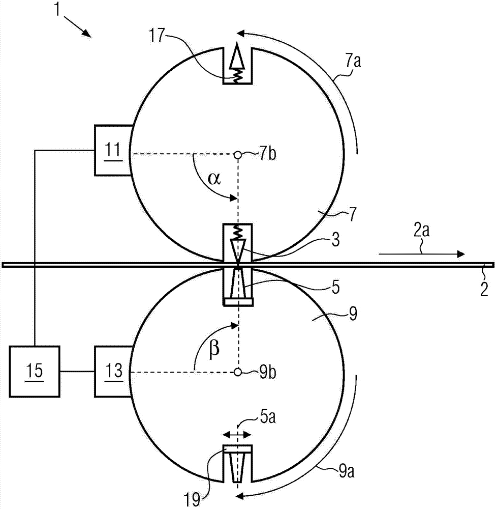
[0029] Such as figure 1It can be seen that the first embodiment 1 of the device according to the invention for the perforation of the film 2 comprises at least one cutting element 3 and at least one counter-cutting element 5 , through which the contact of the cutting element and the counter-cutting element with the film 2 results in an Make punch holes in. Preferably, the cutting element 3 is arranged on a cutting roller 7 with a direction of rotation 7 a or on another rotatable holding device, and the counter cutting element 5 is arranged on a corresponding cutting roller 9 with a direction of rotation 9 a or on another rotatable holding device device, wherein the axes of rotation 7b and 9b are oriented parallel to each other. In addition if figure 1 As indicated, on the cutting roller 7 , in particular at least two cutting elements 3 are distributed uniformly around the periphery, and on the counter-cutting roller 9 there is a corresponding number of counter-cutting elemen...
PUM
 Abstract
Description
Claims
Application Information