Separation method

A separation and rectification separation technology, applied in the field of separation, can solve the problems of insignificant complexity, high investment cost and operation cost, temperature fluctuation at the bottom of the demethanizer, etc., and achieve great flexibility, effective method flow, process technically simple effect

Inactive Publication Date: 2011-01-19
LINDE AG
View PDF11 Cites 3 Cited by
  • Summary
  • Abstract
  • Description
  • Claims
  • Application Information

AI Technical Summary

Problems solved by technology

But this requires relatively high investment and operating costs, and makes such methods unavoidably complicated
Furthermore, it should be noted that temperature fluctuations in the hydrocarbon-rich fraction to be separated lead to fluctuations in the bottom temperature of the demethanizer as well, and at the same time it is not possible to provide C 2 or C 3 product

Method used


Image

  • Separation method
  • Separation method

Examples


Embodiment Construction

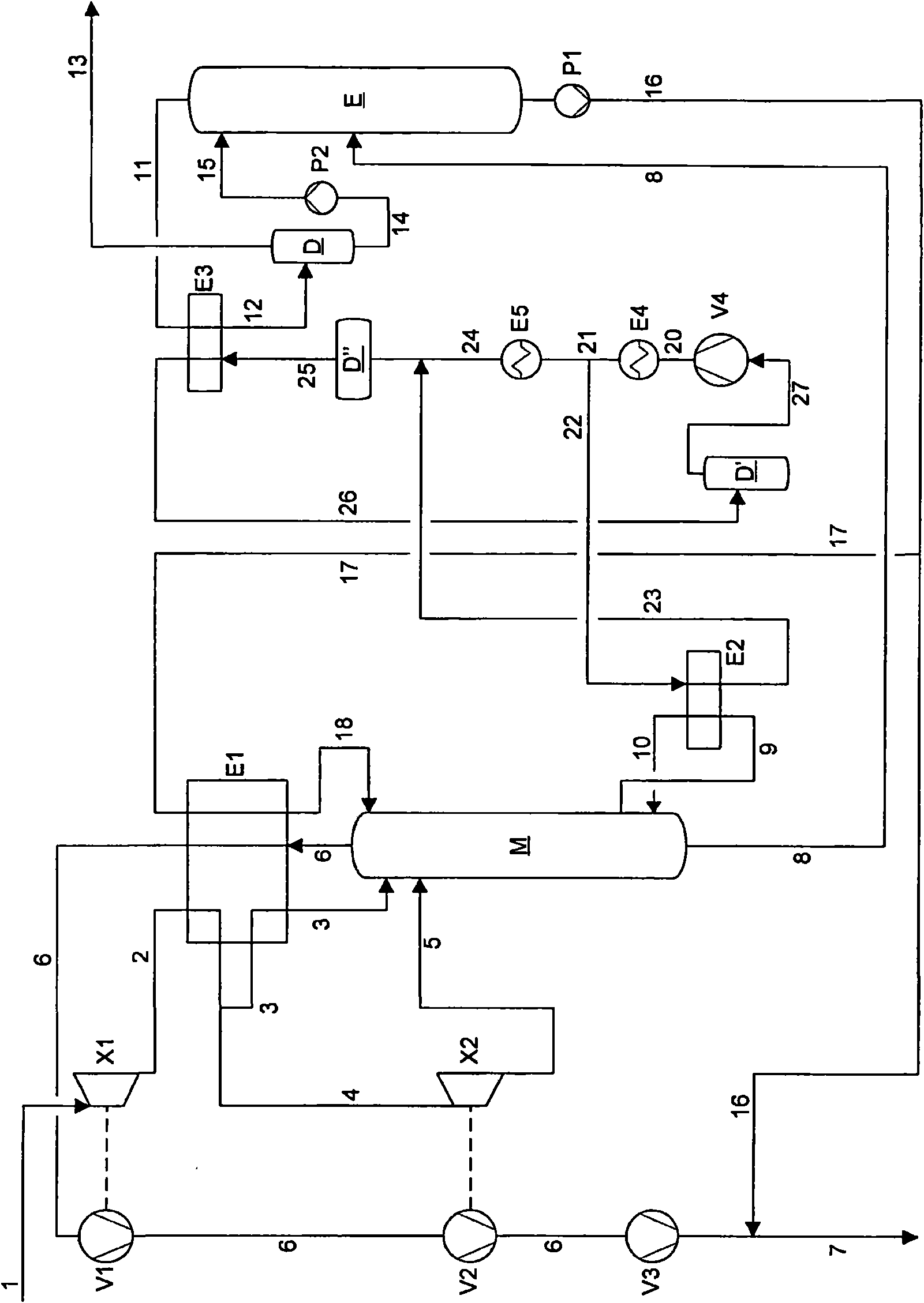
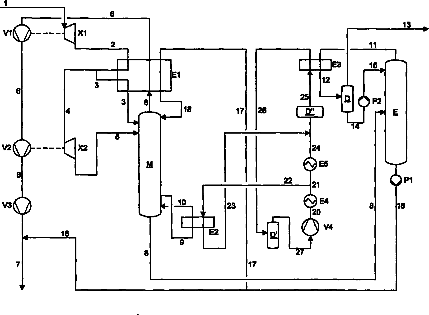
[0016] The hydrocarbon-rich fraction is sent via line 1 to the first expansion turbine X1. The pressure of the hydrocarbon-rich fraction is preferably between 70 and 120 bar. If necessary, the hydrocarbon-rich fraction is subjected to a pretreatment not shown in the figures, in which undesired components such as water and glycols are removed.

[0017] The hydrocarbon-rich fraction depressurized in the first expansion turbine X1 is fed via line 2 to heat exchanger E1 where it is cooled against itself. After discharge from the heat exchanger E1 , the hydrocarbon-rich fraction is divided into two partial streams 3 and 4 . The first partial stream 3 is fed to the top of the demethanizer M after further cooling and complete condensation in the heat exchanger E1.

[0018] The second partial stream 4 is decompressed in the second expansion turbine X2 and then likewise fed via line 5 to the top region of the demethanizer M. In this case, the entry point of the second partial flow i...


PUM


Abstract

A method is described for separating a C2-, C2/CO2-, C2+-, or C3+-rich fraction from a hydrocarbon-rich fraction, wherein the hydrocarbon-rich fraction is depressurized in a single- or multi-stage fashion and subjected to a rectifying methane separation, and the methane-depleted fraction gained from the methane separation is subjected to a rectifying C2, C2/CO2, C2+ or C3+ separation. According to the invention, the sump heating (E2) of the rectifying methane separation (M) is connected via a C3 refrigeration circuit (V4, E4, E5, 20 - 27) to the head cooling (E3) of the rectifying C2, C2/CO2, C2+ or C3+ separation (E).

Description

technical field [0001] The present invention relates to the separation of C-rich 2 、C 2 / CO 2 、C 2+ or C 3+ The method of the fraction, wherein one or more stages of decompression is carried out to the fraction rich in hydrocarbons, methane is rectified and separated, and the fraction depleted of methane obtained in methane separation is subjected to rectified separation C 2 、C 2 / CO 2 、C 2+ or C 3+ . Background technique [0002] After separating the C-rich fraction from the hydrocarbon-rich fraction 2 、C 2 / CO 2 、C 2+ or C 3+ The fundamental requirement present in the fractionation process is to utilize the existing cooling supply as efficiently as possible. This takes place at high raw gas pressures, typically greater than 60 bar, wherein the hydrocarbon-rich fraction is depressurized in one or more stages. If several expansion turbines are used for this purpose, they can be arranged in parallel and / or in series. [0003] If the pressure of the hydrocarbon...

Claims


Application Information

Patent Timeline
Patent Type & Authority Applications(China)
IPC IPC(8): B01D3/14B01D3/32C07C7/04C07C9/04
CPCF25J2215/62F25J3/0242F25J3/0238F25J2215/02F25J2200/04F25J2235/60F25J3/0209F25J2200/02F25J2200/78F25J2200/74F25J2200/70F25J2270/60F25J2240/02F25J2205/50F25J2270/12F25J2220/66F25J3/0233F25J2245/02C10G7/00F25J2240/04F25J2260/02
Inventor H·施密特
Owner LINDE AG
Why Eureka
Try Eureka