

Conveyance device
A technology of equipment and control equipment, applied in the direction of conveyors, mechanical conveyors, transportation and packaging, etc.
- Summary
- Abstract
- Description
- Claims
- Application Information
AI Technical Summary
Problems solved by technology
Method used
Image

Examples
Embodiment Construction
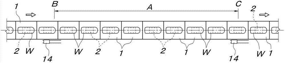
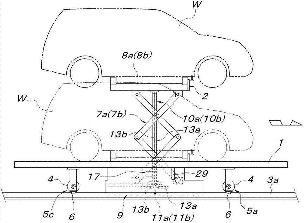
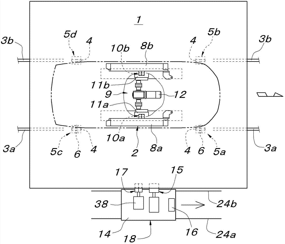
[0027] exist figure 1 Among them, 1 is a traveling body for transportation in the form of a ground trolley, which travels on a certain travel path forming an automobile assembly line in a continuous state facing each other. Each conveyance running body 1 is provided with a movable object support base 2 , and a vehicle body W of an assembled vehicle is mounted on the object support base 2 . In addition, a plurality of work areas are set in the fixed travel path, and the height of the vehicle body W supported and conveyed in each work area can be set to a height suitable for the work in each work area. That is, when each conveying body 1 passes through such as figure 1 When setting the location B on the entrance side of the working area A shown, the conveyed object support platform 2 on each moving body 1 is lifted to the height set at the working area A, and when each moving body 1 When passing through the set point C on the exit side of the working area A, the conveyed objec...
PUM
 Abstract
Description
Claims
Application Information