

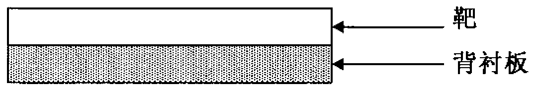
Sputtering target-backing plate assembly
A backing plate and sputtering target technology, which is applied in sputtering coating, electrical components, circuits, etc., can solve problems such as delamination of joints, inherent problems of undisclosed magnetic material targets, temperature rise, etc., to achieve stable supply, Effect of reducing raw material costs and stabilizing sputtering
- Summary
- Abstract
- Description
- Claims
- Application Information
AI Technical Summary
Problems solved by technology
Method used
Image

Examples
Embodiment 1)
[0082] Prepare Co powder with an average particle size of 1 μm, Cr powder with an average particle size of 2 μm, Pt powder with an average particle size of 2 μm, and SiO with an average particle size of 1 μm 2 powder and CoO powder with an average particle size of 3 μm, these raw material powders are Co-17Cr-15Pt-5SiO 2 -8CoO (mol%) was blended, and these powders were mixed with a mixer to obtain a mixed powder of a magnetic material target.
[0083]On the other hand, for the backing plate, Co powder with an average particle size of 1 μm, Cr powder with an average particle size of 2 μm, and SiO powder with an average particle size of 1 μm were prepared in the same manner. 2 powder (in addition, the particle size of these powders will not be particularly problematic, so it is not listed, but the remaining powder of the target can be used; the same below), these powders are Co-25Cr-9SiO 2 (mol %), the compounded powder is hot-pressed, and then machined to obtain a backing plate...
Embodiment 2)
[0097] Co powder with an average particle size of 1 μm, Cr powder with an average particle size of 2 μm, Pt powder with an average particle size of 2 μm, and SiO powder with an average particle size of 1 μm were prepared as in Example 1. 2 powder and CoO powder with an average particle size of 3 μm, these raw material powders are made of Co-17Cr-15Pt-5SiO as a target composition 2 -8CoO (mol %) is compounded, and these powders are mixed with a mixer to produce a powder of a magnetic material target.
[0098] On the other hand, as for the backing plate, Co powder, Cr powder, and SiO 2 powder, these powders are made into Co-25Cr-9SiO 2 (mol %), the blended powder is hot-pressed, and then machined to obtain a backing plate.
[0099] As a result of measuring the magnetic permeability of the backing plate with a B-H meter (analyzer), the magnetic permeability was 1.0. The magnetic permeability of the target is much higher than that.
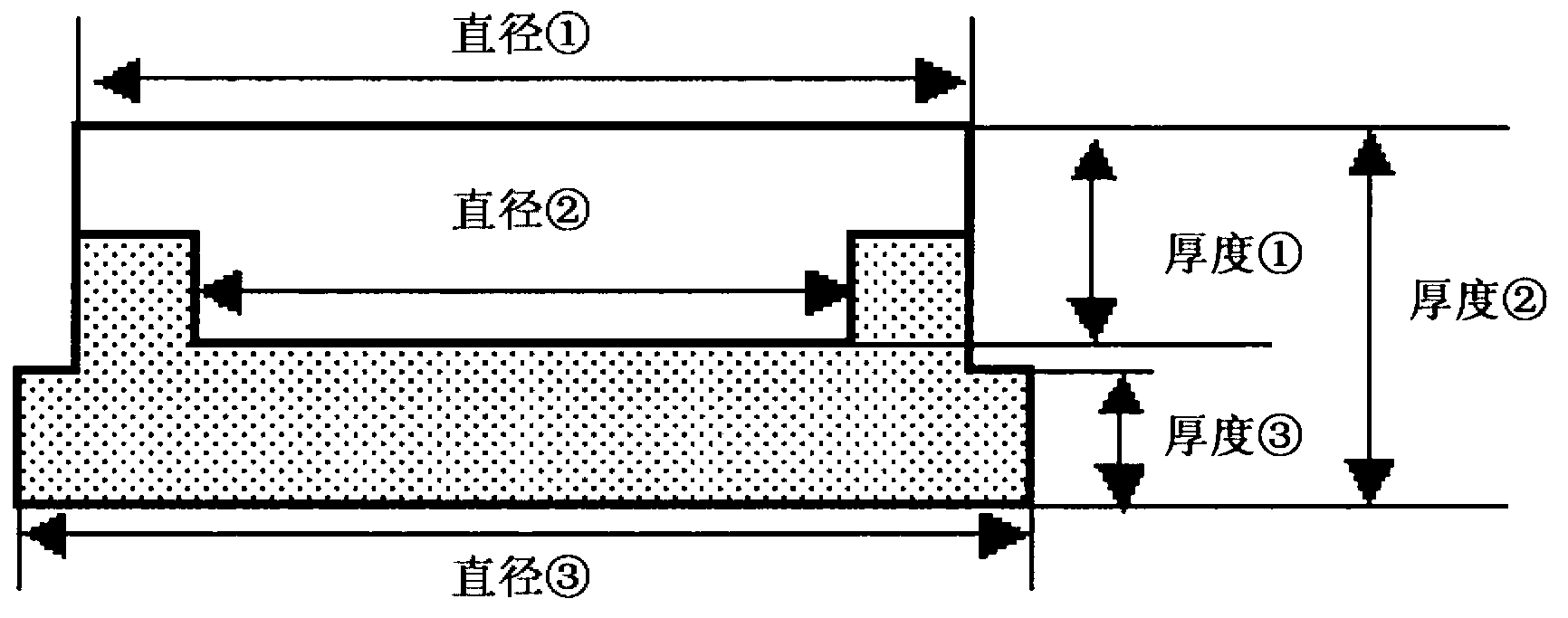
[0100] The shape of the backing plate is se...
Embodiment 3)
[0104] Prepare Co powder with an average particle size of 1 μm, Cr powder with an average particle size of 2 μm, Pt powder with an average particle size of 2 μm, Ru powder with an average particle size of 3 μm, and TiO with an average particle size of 1 μm 2 powder and CoO powder with an average particle size of 3 μm, these raw material powders are Co-15Cr-18Pt-5Ru-4TiO 2 -8CoO (mol%) is compounded, and these powders are mixed with a mixer to manufacture the raw material powder of the magnetic material target.
[0105] On the other hand, as for the backing plate, Co powder, Cr powder, and SiO 2 powder, these powders are made into Co-25Cr-10SiO 2 (mol%), the backing plate material is hot-pressed, and then machined to produce a backing plate.
[0106] As a result of measuring the magnetic permeability of the backing plate with a B-H meter (analyzer), the magnetic permeability was 1.0. The magnetic permeability of the target is much higher than that.
[0107] Then, the backin...
PUM
| Property | Measurement | Unit |
|---|---|---|
| diameter | aaaaa | aaaaa |
| diameter | aaaaa | aaaaa |
Abstract
Description
Claims
Application Information