Electric glass knapper

A glass breaking and electric technology, which is applied in the direction of vehicle safety arrangement, life-saving equipment, pedestrian/passenger safety arrangement, etc., can solve problems such as breaking difficulties

Inactive Publication Date: 2012-12-12
肖玲
View PDF6 Cites 6 Cited by
  • Summary
  • Abstract
  • Description
  • Claims
  • Application Information

AI Technical Summary

Problems solved by technology

It is very difficult to break with a glass breaker such as a hand hammer

Method used


Image

  • Electric glass knapper
  • Electric glass knapper
  • Electric glass knapper

Examples


Embodiment 1

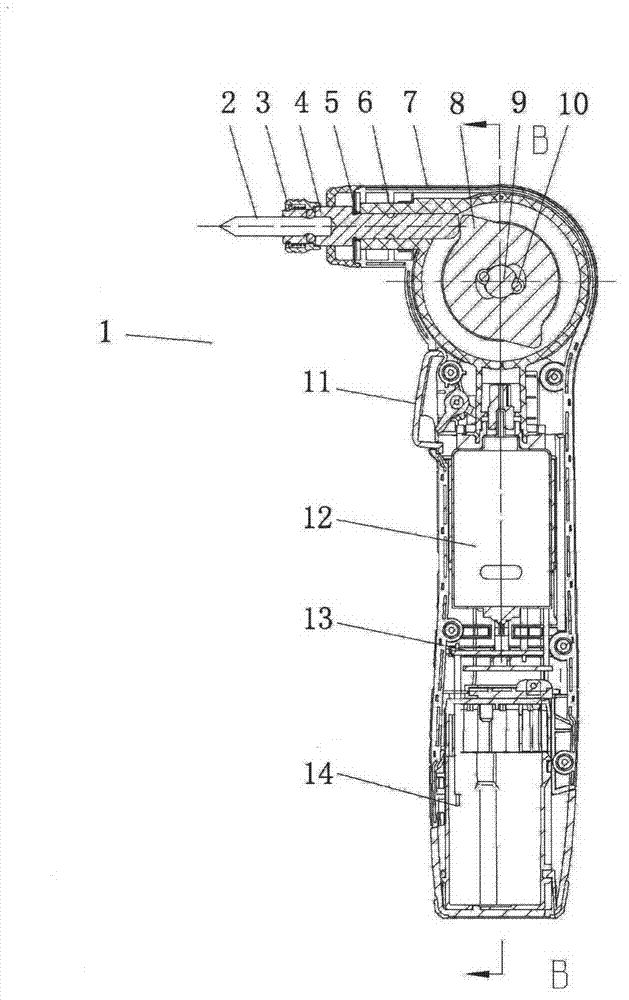
[0014] The electric glass breaker 1 of the present embodiment is as figure 1 , 2 , 3, including:

[0015] Case 7, the case is shaped into a "7" shape with a handle at the lower part, and the top of the handle has a terminal protruding forward;

[0016] The power device is composed of a motor 12 located in the casing, and the motor 12 is placed in the handle part of the casing 7 with the main shaft vertical;

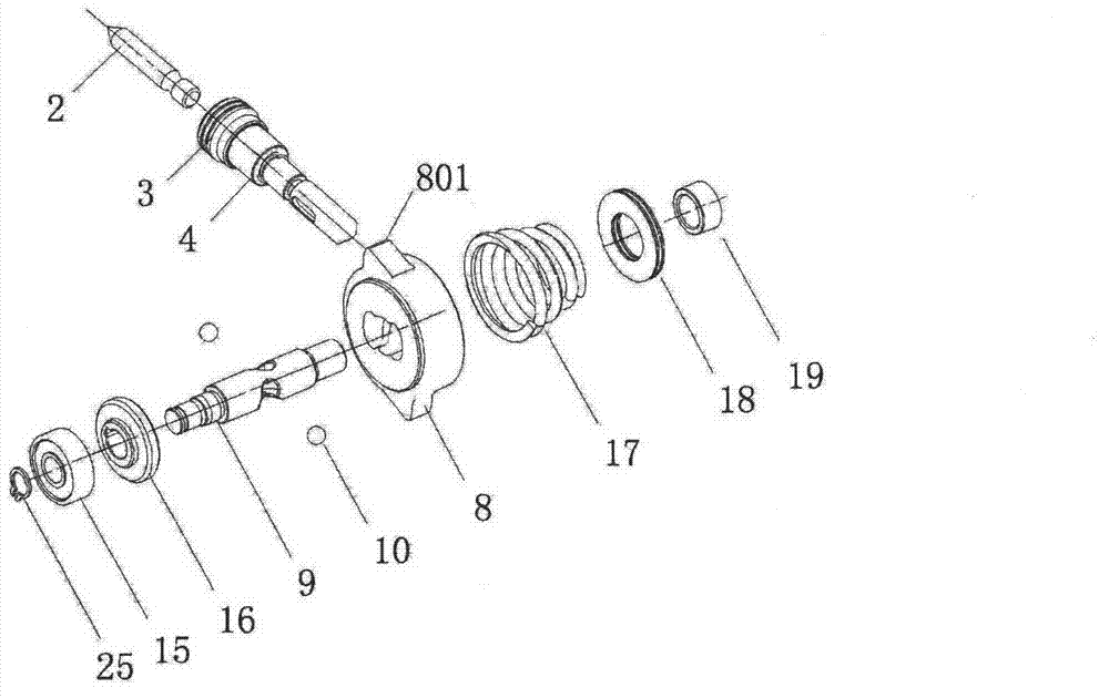
[0017] The actuator is composed of an energy storage spring 17 with compressed energy storage and energy release tending to return to a natural state, an impact block 8 as a striking component, and a striking rod assembly as an executing component; the striking rod assembly consists of an output shaft 4, a collet 3 and the striking rod 2;

[0018] The transmission device is composed of a gearbox 6 as a speed change mechanism, which is used to connect the power device and the actuator;

[0019] The control device is composed of a motor on-off control switch 11 as a con...

Embodiment 2

[0025] The electric glass breaker of the present embodiment is as Figure 4 As shown, its basic structure is the same as that of Embodiment 1, the main difference is that the casing is hand-held, and the end of the casing protruding forward supports a retractable impact shaft 26, which is equivalent to that of Embodiment 1. The output shaft of the utility model is connected with the striking rod to form a whole, so the structure is simpler.

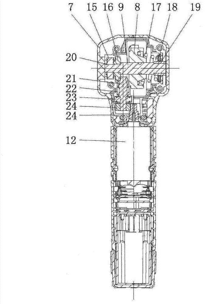
[0026] In order to further elaborate on the above-mentioned embodiment, more specifically: the transmission mechanism is composed of a pair of spur gears and a pair of bevel gears, the large bevel gear 16 is installed on the main shaft 9, the main shaft 9 is supported by the bearing A15 and the bearing B19, and the The impact block 8 and the thrust bearing 18 are set, and the energy storage spring 17 is installed between the impact block 8 and the thrust bearing 18 .

[0027] After the switch is turned on, the motor 12 drives the small s...


PUM


Abstract

The invention discloses an electric glass knapper and belongs to the technical field of fire escape tools. The knapper comprises a handle with a built-in motor in an enclosure, wherein a main shaft driven by a horizontal motor through a transmission mechanism is supported on the upper part of the handle, an impact block with a radial projection is sleeved on the main shaft, and one side of the impact block props against on an energy storage spring; a telescopic collision element extending forwards is supported at a position corresponding to the radial projection on the enclosure, when in use, the back end of the collision element tends to prop against the projection of the impact block, and a helical groove for holding an engaging element and a depression are respectively arranged on the excircle of the main shaft and the inner hole of the impact block; and when the main shaft rotates, the impact block has a rotation prevention state of being periodically pushed by the helical groove through the engaging element in the axial direction to compress the energy storage spring and a rotation state of quickly resetting when the energy storage spring is compressed to the limit position and rotates along with the main shaft. The electric glass knapper disclosed by the invention can be used for quickly breaking the current high strength toughened glass under the impact function of the high-frequency huge collision force so as to open the escape passage.

Description

technical field [0001] The invention relates to a glass breaker, in particular to an electric glass breaker, which belongs to the technical field of fire escape tools. Background technique [0002] As far as the applicant knows, the existing glass breakers are manual hammers or manual spring energy storage hammers. When in use, not only the striking force is limited, especially the striking frequency is limited, so only thin glass can be broken. At present, the glass curtain walls of high-rise buildings are usually tempered glass with a thickness of more than 10mm, and some are even double-layer laminated glass. It is very difficult to break it with a glass breaker such as a hand hammer. When running into accidents such as fire, the event that trapped personnel cannot escape for this reason occurs frequently, and even firefighters are also buried in a sea of ​​flames because of this. Therefore, there is an urgent need for a fast and high-energy glass breaker to replace th...

Claims


Application Information

Patent Timeline
Patent Type & Authority Applications(China)
IPC IPC(8): A62B3/00B60R21/02
Inventor 肖玲
Owner 肖玲
Why Eureka
Try Eureka