
Hose feeding self-locking and conveying device of hose assembling machine

A conveying device and assembly machine technology, applied in metal processing, metal processing equipment, manufacturing tools, etc., can solve problems such as slipping and shorten assembly time, and achieve the effects of saving production costs, enhancing competitiveness, and increasing production capacity

Active Publication Date: 2012-12-12
广西自由贸易试验区良维电子有限公司
View PDF7 Cites 3 Cited by
  • Summary
  • Abstract
  • Description
  • Claims
  • Application Information

AI Technical Summary

Problems solved by technology

[0005] The purpose of the present invention is to overcome the above-mentioned defects, provide a hose assembly machine that can put more than one hose assembly at a time, and does not need to be taken out manually after the assembly is completed, and solves the problem that a pair of hands cannot be put in at the same time. Multiple hoses need to be put in sequence. The first hose will slip off. We invented a method that automatically locks the hose and prevents it from slipping as long as the hose is placed in the upper material position without the support of both hands. The hose loading self-locking device and the automatic conveying device that can automatically send the hose to the assembly station effectively shorten the assembly time and improve the assembly efficiency

Method used


Image

  • Hose feeding self-locking and conveying device of hose assembling machine
  • Hose feeding self-locking and conveying device of hose assembling machine
  • Hose feeding self-locking and conveying device of hose assembling machine

Examples


Embodiment Construction

[0020] The following are specific embodiments of the present invention and in conjunction with the accompanying drawings, the technical solutions of the present invention are further described, but the present invention is not limited to these embodiments.

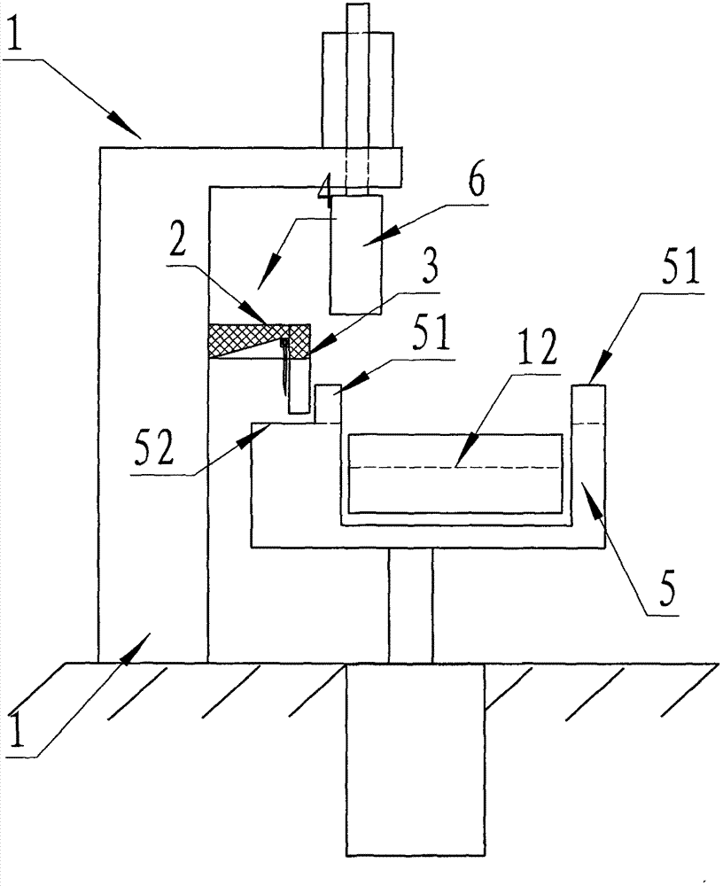
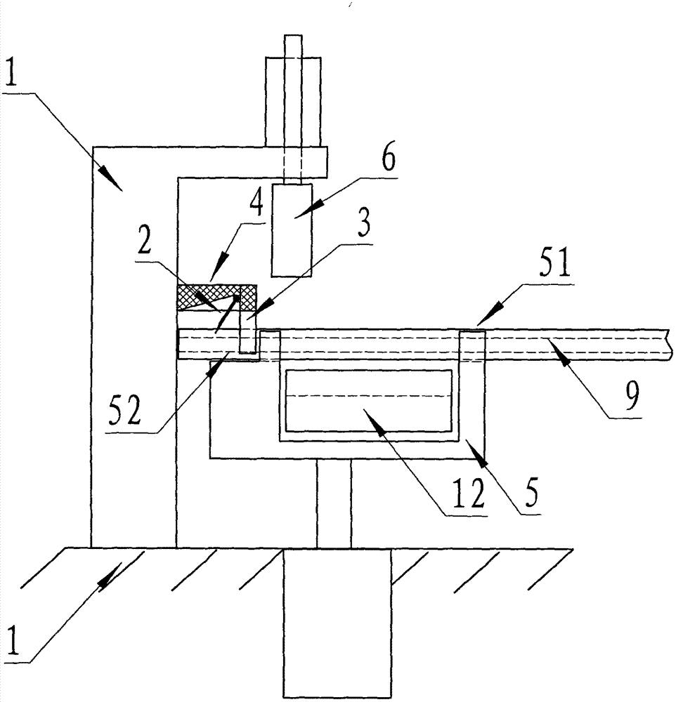
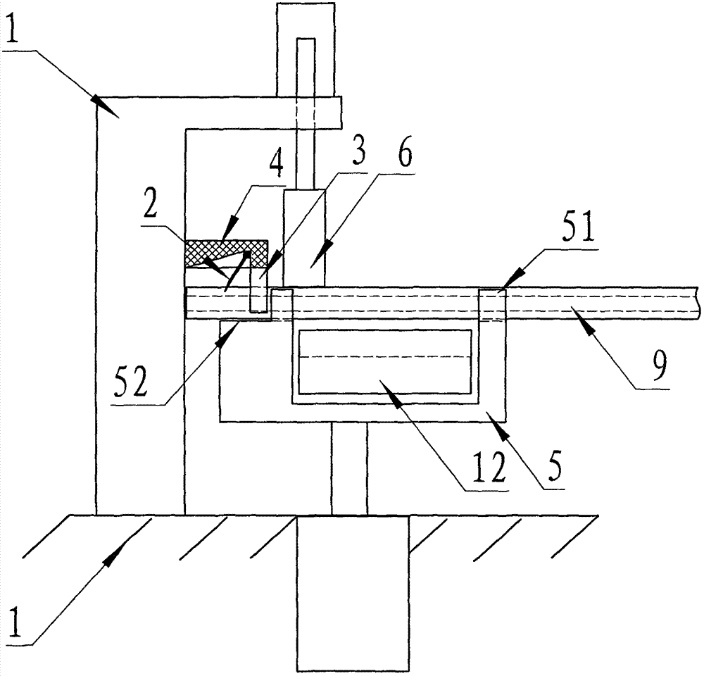
[0021] Such as Figure 1-Figure 6 As shown, the socket piece 3 and the feeding movable mechanism 5 for inserting at least one or more hoses 9, several locking pieces 2 for automatically locking several hoses 9, and the fixing for fixing the locking piece 2 part 4 and a presser 6 for pressing and pasting several hoses 9 without slipping; the socket part 3 is fixedly connected with the fixing part 4, and the fixing part 4 is fixedly connected on the hose assembly machine frame 1, located on Above the upper plane of the feeding movable mechanism 5, the lower end surface of the socket part 3 is close to the upper plane when the feeding movable mechanism 5 rises. The two sides of the mechanism 12 move up and down, and the ...


PUM


Abstract

The invention relates to a hose feeding self-locking and conveying device of a hose assembling machine. The hose feeding self-locking and conveying device is arranged at upper ends of hoses on lateral upper sides of feed inlets of a hose conveying mechanism on a cabinet rack of the hose assembling machine. The hose feeding self-locking and conveying device is characterized by comprising a plurality of socket parts, a feeding movable mechanism, a plurality of locking plates, fixing parts and a pressing device; more than one hose is inserted in the socket parts; the locking plates are used for automatically locking the hoses; the fixing parts are used for fixing the locking plates, and the pressing device is used for pressing the hoses to prevent the hoses from slipping. The hose feeding self-locking and conveying device solves difficult problems that multiple hoses cannot be simultaneously placed in both hands of a worker, and if the hoses are placed in the hose assembling machine sequentially, the hoses placed in the hose assembling machine previously can slip out of the hose assembling machine. By the hose feeding self-locking and conveying device, the hoses only need to be placed into the feeding positions and then can be automatically locked and do not slip off again without holding by hands of workers, the automatic conveying device can realize feeding self-locking and can automatically convey the hoses to assembling positions, assembling time is effectively shortened, and assembling efficiency is improved.

Description

technical field [0001] The invention belongs to the technical field of valve fluid machinery, and relates to a hose assembly machine, in particular to a hose feeding self-locking and conveying device of the hose assembly machine. Background technique [0002] In the valve fluid hose machinery, the hose joint is widely used in the assembly connection of various water heating pipelines and various gas hydraulic pipelines, and the connection and installation are convenient and fast; [0003] At present, in the hose industry, manual operation is mainly used for the assembly of hose joints, and the work content is mainly to insert steel sleeves, cores, nuts and other parts at both ends of the hose. Because the braided wire of the hose braid elastically spreads out at the incision part, it is very sharp, and workers are often stabbed by metal wires during the assembly process, and the requirements for the proficiency of the workers are high, the labor intensity is high, the ...

Claims


Application Information

Patent Timeline
IPC IPC(8): B23P19/00
Inventor 丁伟兴
Owner 广西自由贸易试验区良维电子有限公司
Learn More