Control device for hydraulic winch and engineering machine

A control device and hydraulic winch technology, applied in the hydraulic field, can solve problems such as unstable speed and achieve the effect of stable control

Active Publication Date: 2012-12-12
SHANGHAI ZOOMLION HEAVY IND PILING MACHINERYCO +1
View PDF7 Cites 14 Cited by
  • Summary
  • Abstract
  • Description
  • Claims
  • Application Information

AI Technical Summary

Problems solved by technology

[0007] The present invention aims to provide a control device and a drilling rig for a hydraulic winch,

Method used


Image

  • Control device for hydraulic winch and engineering machine
  • Control device for hydraulic winch and engineering machine
  • Control device for hydraulic winch and engineering machine

Examples


Embodiment Construction

[0028] The embodiments of the present invention will be described in detail below with reference to the accompanying drawings, but the present invention can be implemented in many different ways defined and covered by the claims.

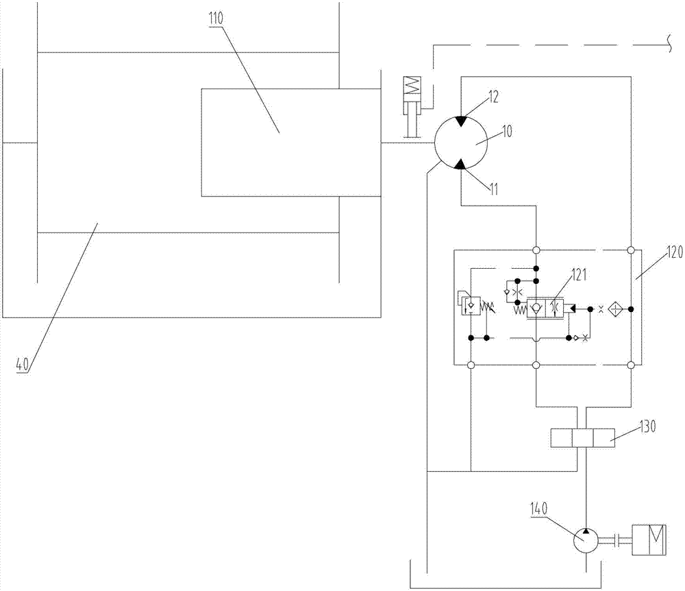
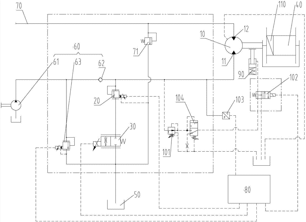
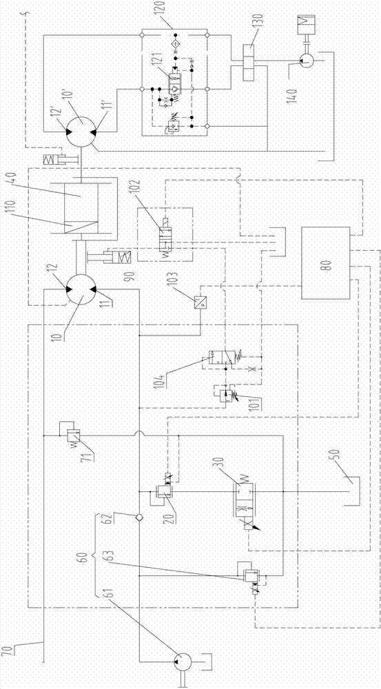
[0029] As a first aspect of the present invention, a control device for a hydraulic winch is provided. Such as figure 2 with image 3 As shown, the control device includes a motor 10, a back pressure valve 20 and a flow regulating valve 30; the motor 10 is connected with a hydraulic winch 40, and the motor 10 includes a load chamber 11 and a descending chamber 12; the load chamber 11 is sequentially connected with the back pressure valve 20, the flow rate The regulating valve 30 is connected with the oil tank 50 . Preferably, the motor 10 is connected to the reel of the hydraulic winch 40 through a reducer 110 . Therefore, in the case where a slow descent is required, a reducer with a larger reduction ratio is used, and the slow descent is easier...


PUM


Abstract

The invention provides a control device for a hydraulic winch and an engineering machine. The control device comprises a motor, a back pressure valve and a flow regulation valve, wherein the motor is connected with the hydraulic winch, and comprises a loading cavity and a descending cavity; and the loading cavity is connected with the back pressure valve, the flow regulation valve and an oil tank sequentially. According to the control device, the flow regulation valve is used for regulating the flow of hydraulic oil discharged from the loading cavity of the motor, so that the control on a descending speed is realized, the speed of slow descending is controlled stably, and the control is more stable and reliable.

Description

technical field [0001] The invention relates to the field of hydraulics, and more specifically, to a control device for a hydraulic winch and construction machinery. Background technique [0002] Vertical earth and stone excavation construction (such as drilling down from the surface, tunneling, etc.) needs to control the speed of drilling / driving, and the pressure of drilling / driving equipment (ie, load) on the ground. When the drilling / excavation working device is suspended by a hydraulic winch, the speed of drilling / excavation and the pressure control of the drilling / excavation working device on the ground can be controlled by controlling the speed of the hydraulic winch (that is, the speed of descent) and the speed on the rope. Drag is achieved. [0003] figure 1 A hydraulic principle diagram of a control device of a hydraulic winch in the prior art is shown. Such as figure 1 As shown, the reel of the hydraulic winch 40 is connected to the motor 10 through a reducer ...

Claims


Application Information

Patent Timeline
IPC IPC(8): B66D1/08B66D1/44
Inventor 朱长林乔国华黄志明刘发民
Owner SHANGHAI ZOOMLION HEAVY IND PILING MACHINERYCO
Why Eureka
Try Eureka