
Movable floated bioreactor

A bioreactor and suspension technology, which is applied in the field of mobile suspension bioreactors, can solve the problems of high cost of bioreactors, high cost of large water areas, high operating costs, etc., to reduce structural costs, reduce transportation costs, The effect of excellent performance

Active Publication Date: 2014-05-07
项栋才 +2
View PDF5 Cites 0 Cited by
  • Summary
  • Abstract
  • Description
  • Claims
  • Application Information

AI Technical Summary

Problems solved by technology

[0005] The present invention aims at many problems such as excessive cost of applying biological treatment methods to treat large-area waters, high cost of existing bioreactors, high energy consumption, and high operating costs.

Method used


Image

  • Movable floated bioreactor
  • Movable floated bioreactor
  • Movable floated bioreactor

Examples


Embodiment 1

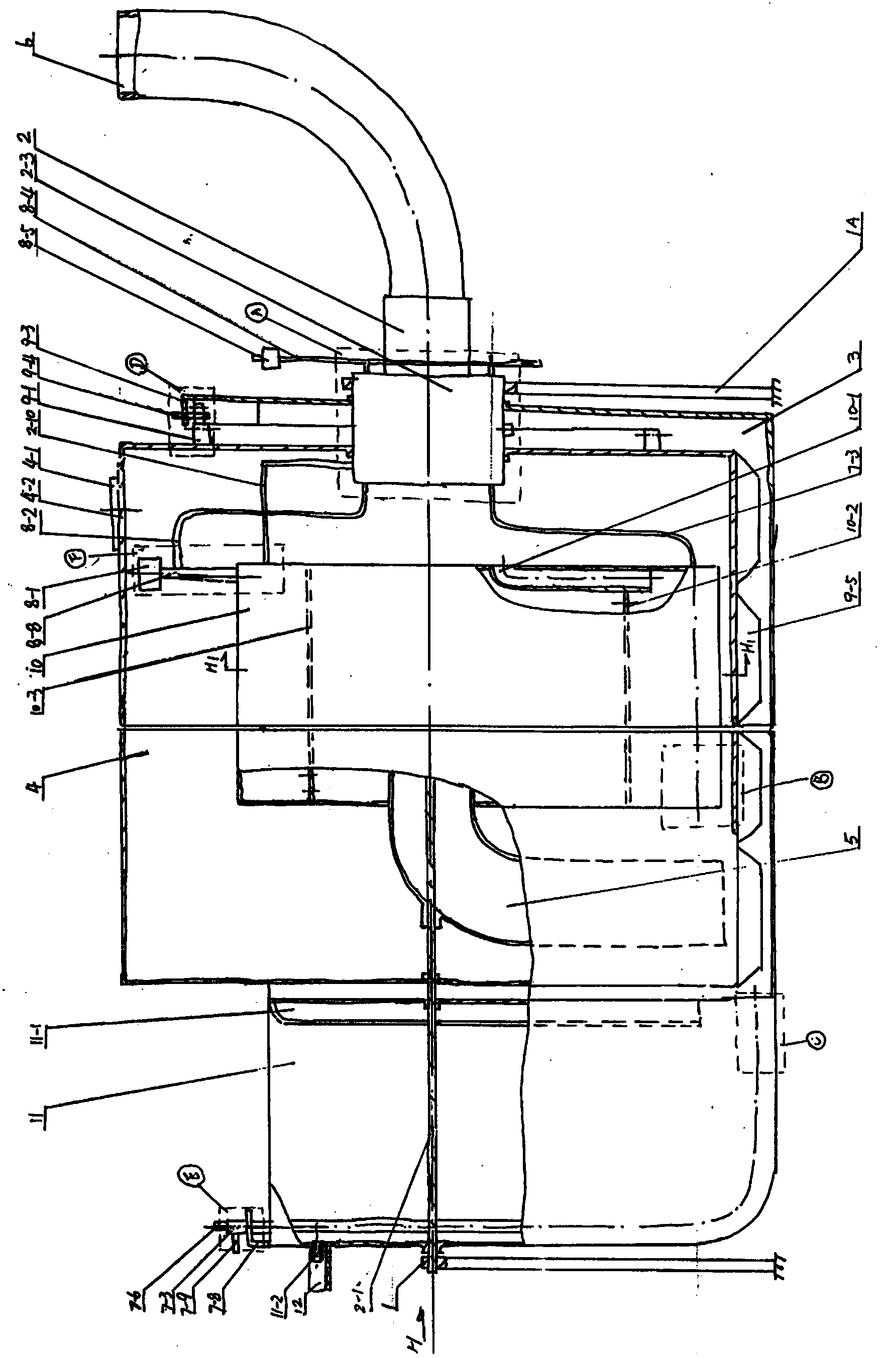
[0040] A movable suspended tube-barrel bioreactor.

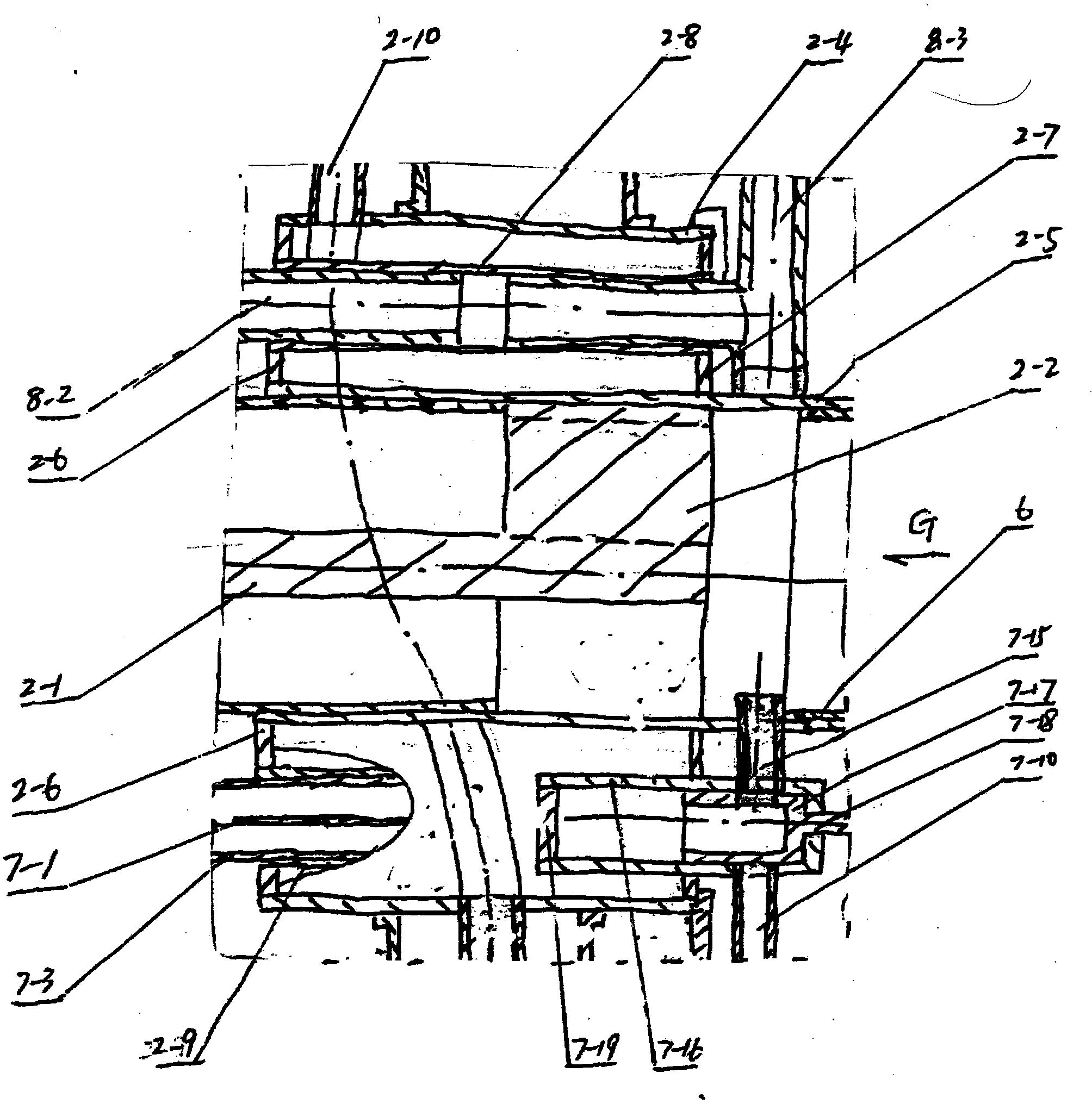
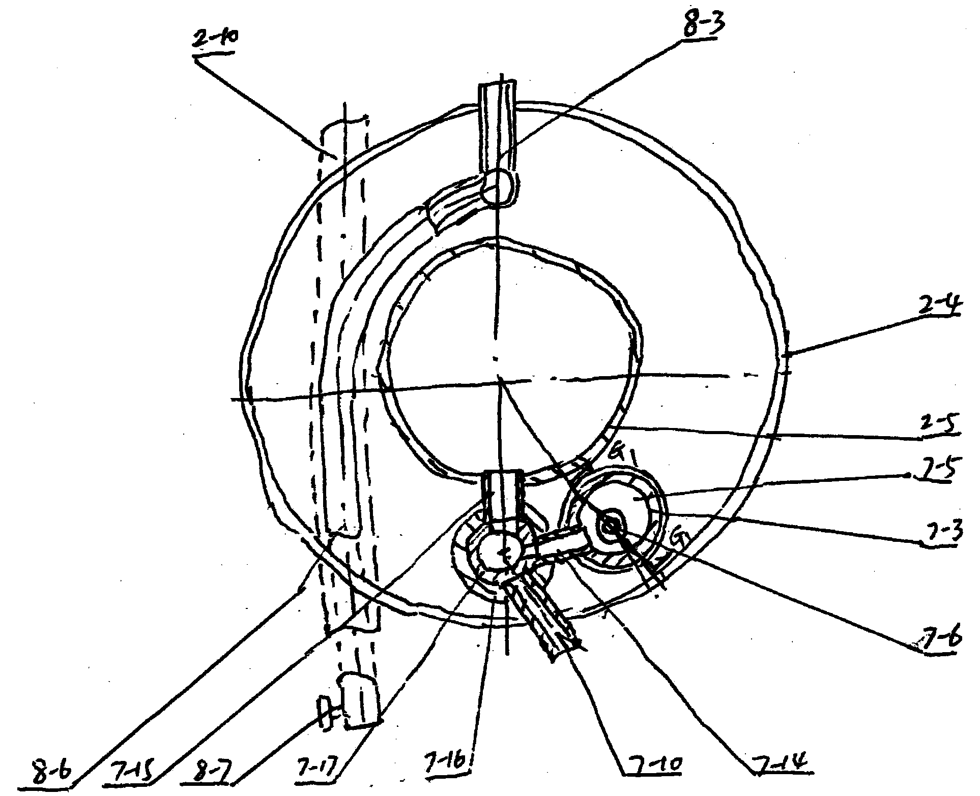
[0041] Suspension tube-barrel-shaped rolling stirring bioreactor, including support, supporting device, outer tank, inner tank, sedimentation tank, raw meal reaction tank, feeding pipe, mud pumping device, gas collecting device, and stirring device. The horizontal support device supported by the left and right brackets that are fixedly connected with the bottom of the water body is hoisted with an upper open tube barrel-shaped outer pool, and the material liquid and the horizontal support device in it jointly support the flow through the material liquid. There is an installation window and a cover. The outer wall of the plate cover is provided with a series of openings. The outer wall of the apron is provided with a round tube or disc-shaped gear, which is adapted and meshed with the driving gear installed on the outer pool wall bracket, and is driven by it to work around the axis of the supporting device. Rolling and rotati...

Embodiment 2

[0054] Multiple mobile suspension bioreactors driven by fans.

[0055] Working process: the inner tank 4 located in the sinking-floating tank 3A is jointly supported by the feed liquid in the sinking-floating tank 3A and the support device 2 installed on the sinking-floating tank 3A, and its rolling and stirring is carried out by the support 14A which is fixedly connected with the wall of the sinking-floating tank 3A The fixed fan 13A drives the gear 9-2 and the gear 9-1 to drive the inner tank 4 to complete; the feed liquid in and out: the feed liquid to be treated at the polluted water body, flows to the outside of the sink-float reaction tank 3A through the suspension tank 12A Below the bracket 14 fixedly connected to the wall of the sinking-floating pool 3A, the liquid-drawing device 15 is fixed, and the fan 13 mounted on the bracket 14 drives the suction to be heated by the biogas heating device 16 set outside the liquid-drawing device. to the feed pipe 6, after the anaer...


PUM


Abstract

A movable floated bioreactor is characterized in that an enclosed internal pool is placed in a feed liquid or water body of an openmouthed fixed or floating external pool and axially rotates around a supporting device on a bearing pile which is fixedly installed on the external pool or erected in the water body, so as to be rolled and stirred under the buoyancy of the liquid. The movable floated bioreactor provided by the invention has very strong adaptability, and is suitable for both hundreds, thousands and tens of thousand cubic meters' small, medium-sized, large-scale and ultra-large automatic sewage processing and a dozen and scores of cubic meters' minitype families and alliances for source separation sewage processors and human and animal night soil and straw foreign material processing methane tanks. By the adoption of the movable floated bioreactor, those who pollute are supposed to treat and will benefit from the treatment; discharge is changing into feeding; discharging is carried out if the feed is in need; and harmonious development of the economy, environment and society is promoted. According to the invention, various novel technologies and novel preparations can be rapidly grafted or adopted, and low investment, high yield and cost performance optimization can be realized.

Description

technical field [0001] The invention relates to the field of sewage treatment, in particular to a movable suspension bioreactor. Background technique [0002] Existing sewage treatment mostly adopts high-pressure, high-strength reaction tanks and traditional mixing methods, which are high in cost, high in energy consumption, high in operating costs, high in and out of feed liquid freight, and poor in effect. Some use biological treatment. For example, stocking aquatic plants on the water surface to absorb eutrophication in the water is indeed effective, but after the aquatic plants are harvested, crushed and squeezed, the slurry and block materials are transported to the sewage treatment plant by boat for treatment, which is a waste of time and money. [0003] For large areas of water such as rivers and lakes where eutrophication is relatively serious, biological treatment is currently the most effective treatment method. Stocking aquatic plants on a large area of ​​water,...

Claims


Application Information

Patent Timeline
Patent Type & Authority Patents(China)
IPC IPC(8): C02F3/30
CPCY02W10/33Y02W10/37
Inventor 史继龄
Owner 项栋才
Learn More