Method and apparatus for knit design

A technology of knitting design and knitted fabrics, which is applied in knitting, weft knitting, calculation, etc., and can solve problems affecting pattern design, etc.

Active Publication Date: 2014-08-13
SHIMA SEIKI MFG LTD
View PDF6 Cites 2 Cited by
  • Summary
  • Abstract
  • Description
  • Claims
  • Application Information

AI Technical Summary

Problems solved by technology

In this way, when the target area 2a where the pattern 4 is designed is added with a widening loop 5, it will affect the design of the pattern.

Method used


Image

  • Method and apparatus for knit design
  • Method and apparatus for knit design
  • Method and apparatus for knit design

Examples


Embodiment 1

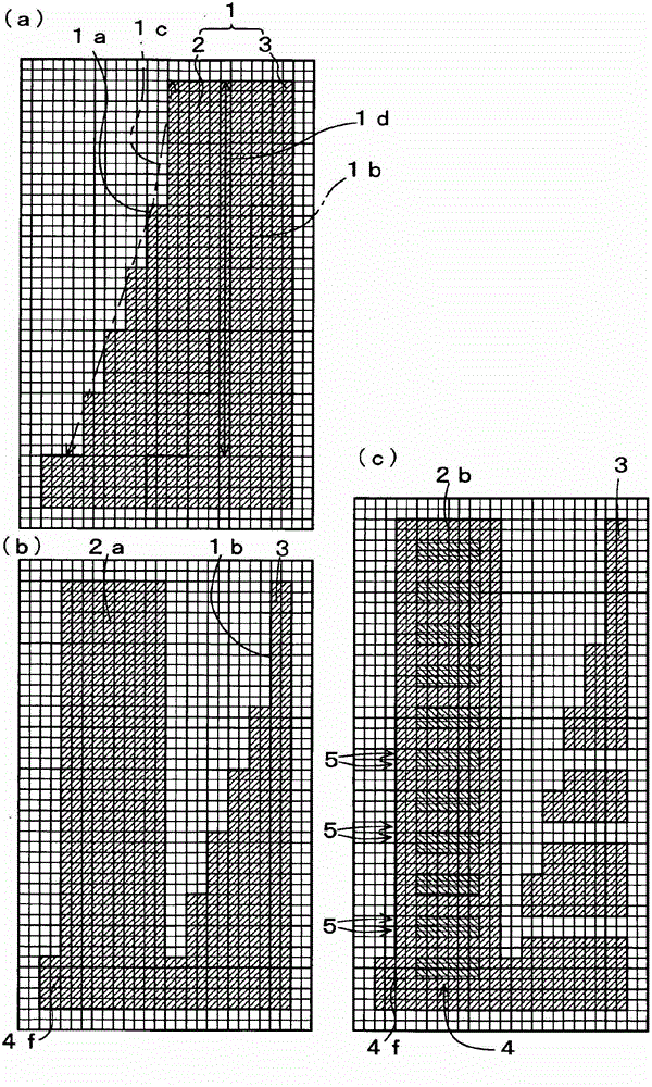
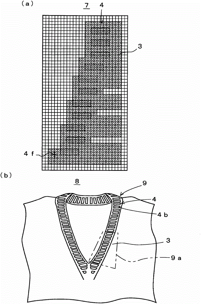
[0059] exist figure 1 In (a), the designated region 2 of double-back knitting in the stitch pattern 1 is set at a constant knitting width of 10 turns from the end, for example. According to this designation, the coil pattern 1 is divided into a designated area 2 and a base area 3 connected to the designated area 2 from the part of the coil pattern 1 other than the designated area 2 . exist figure 1 In (b), the designated area 2 is slid in the course direction to be transformed into a simple shape such as a rectangular target area 2 a. Such division and deformation in Figure 5 (a) and Figure 5 (b) was also performed in the same manner. But when figure 1 In (a), the length 1c of the outer edge 1a of the designated area 2 and the length 1d in the wale direction are considered. in design Figure 5 In the case of pattern 4 shown in (c), pre-set figure 1 Set the starting position 4f in (b), such as figure 1 As shown in (c), the pattern 4 is developed from the start posi...

Embodiment 2

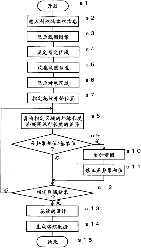
[0073] Figure 4 The schematic structure of the knit designing device 10 which is another embodiment of this invention is shown. The knitting design device 10 is to perform Figure 1 ~ Figure 3 The program of the knit design method shown is implemented by being installed in a widely used computer including a processing device 11 , an input device 12 , a display device 13 and a storage device 14 . The processing device 11 includes a data generation unit 21 , an area dividing unit 22 , a loop adding unit 23 , a pattern design unit 24 and an area connecting unit 25 . The data generation component 21, the area division component 22, the additional loop increase component 23 and the pattern design component 24 respectively correspond to image 3 Step s14, step s4, step s10 and step s13. In addition, the operation corresponding to the area connecting member 25 is also included in step s14. The storage device 14 includes designated area information 26 including various informatio...


PUM


Abstract

The present invention provides a knitting design method and device that can easily add stitches without affecting the design in a state where stitches are added. In (a), the designated area ( 2 ) of double-sided knitting in the stitch pattern ( 1 ) is set, for example, with a constant knitting width of 10 turns from the end. In (b), the start position ( 4 f ) is set, and the designated area ( 2 ) is slid in the course direction to transform into a simple-shaped target area ( 2 a ). In (c), based on the difference between the length (1c) of the outer edge (1a) of (a) and the length (1d) in the wale direction, an additional coil is added to reduce the deformation caused by the difference In the target area (2b) of (5), the pattern (4) is developed from the start position (4f). Since the target area ( 2 b ) in which the pattern ( 4 ) is developed is returned so as to be connected with the base area ( 3 ), the design of the pattern ( 4 ) such as a double-reverse pattern can be not affected.

Description

technical field [0001] The invention relates to a knitting design method and device for designing knitted fabrics woven by a computer-controlled flat knitting machine. Background technique [0002] Conventionally, in flat knitting machines used for production of knitted products, selection of knitting needles, travel of carriages, switching of knitting yarns, etc. are performed by computers based on knitting data created in advance. For creation of knitting data, a knitting design device is used (for example, refer to Patent Document 1). [0003] Figure 5 The basic concept of the knitting design method and its device disclosed in Patent Document 1 and the outline of a pattern design method applying the basic concept are shown. Figure 5 (a) shows the stitch pattern 1 which becomes the basis of the knitted fabric product design. The stitch pattern 1 is displayed as an image on the display device of the knit design device, and the user inputs and generates data for each stit...

Claims


Application Information

Patent Timeline
Patent Type & Authority Patents(China)
IPC IPC(8): D04B35/00G06F17/50
CPCD04B15/70D04B7/26D04B1/126D04B37/02D04B7/24D04B15/66D04B35/00
Inventor 冈崎弘幸岛崎宜纪
Owner SHIMA SEIKI MFG LTD
Why Eureka
Try Eureka