Device for detecting working state of current collector

A working state and detection device technology, applied in the detection field, can solve problems such as low reliability, and achieve the effects of high reliability, simple structure, and not easy to be affected by external factors

Active Publication Date: 2014-08-27
ZHUZHOU ELECTRIC LOCOMOTIVE CO LTD
View PDF5 Cites 0 Cited by
  • Summary
  • Abstract
  • Description
  • Claims
  • Application Information

AI Technical Summary

Problems solved by technology

[0004] The invention provides a working state detection device of a current receiver, which is used to solve the problem of low reliability of the current receiver working state detection device in the prior art

Method used


Image

  • Device for detecting working state of current collector
  • Device for detecting working state of current collector
  • Device for detecting working state of current collector

Examples


Embodiment 1

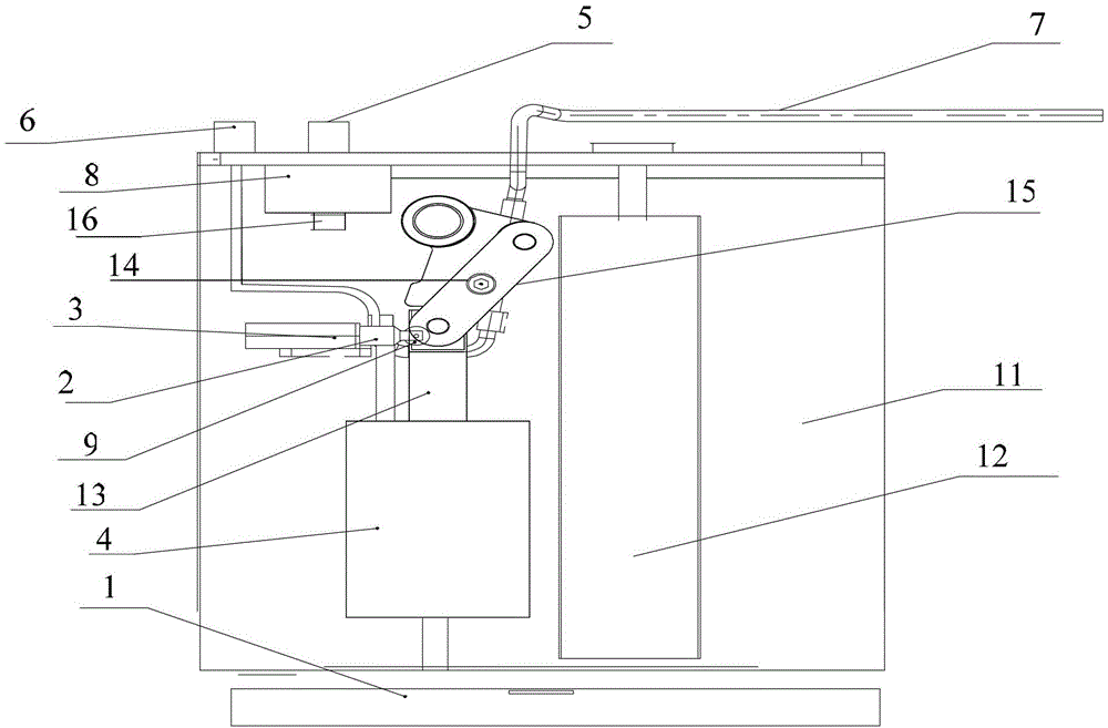
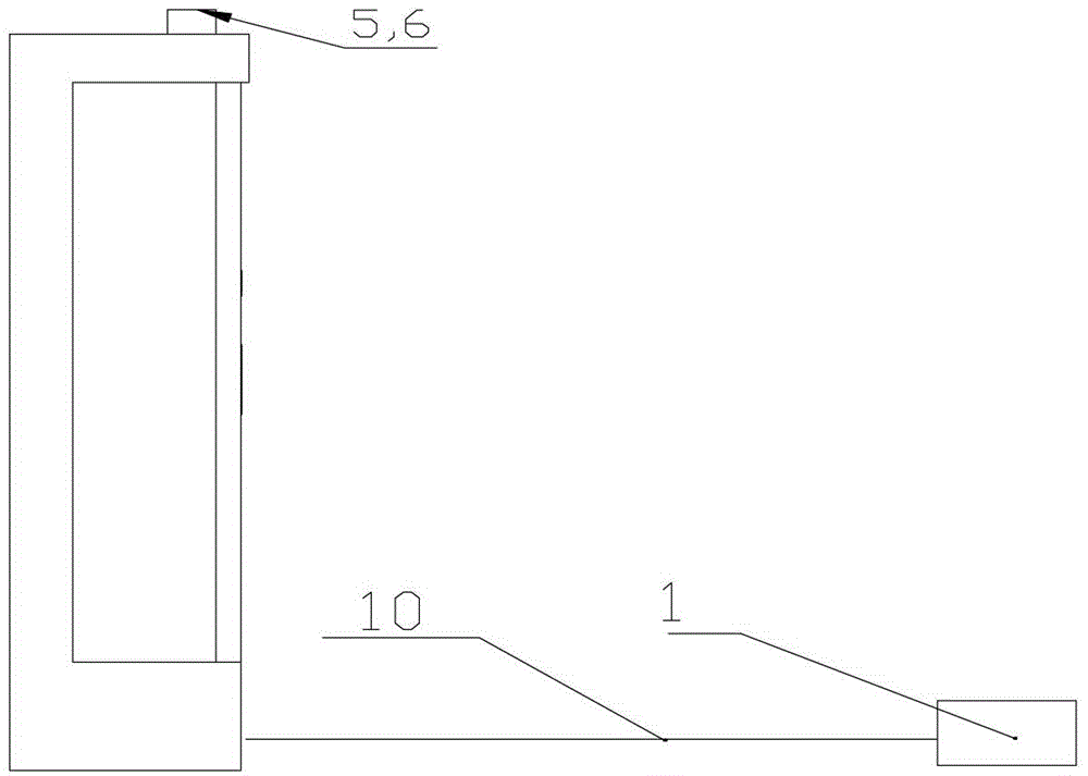
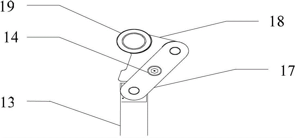
[0021] figure 1 It is the front view of the current receiver installed with the current receiver working state detection device of the present invention, figure 2 It is a side view of a current collector equipped with a current collector working state detection device of the present invention, image 3 It is a structural schematic diagram of the lock mechanism of the receiver.

[0022] Such as figure 1 as well as figure 2 As shown, the current receiver is mainly composed of the collector shoe 1, the isolation cylinder 4, the cylinder pipeline 5, the cylinder pipeline 6, the signal line 7, the unlock cylinder 8, the small wheel 9 of the position indicator 3, the swing arm 10, and the receiver Flow device main body 11, spring 12, isolation cylinder shaft 13, lock mechanism 15 are made up. When the isolation cylinder shaft 13 of the current collector drives the lock mechanism 15 to move downward, the position trigger mechanism 14 and the small wheel 9 of the position indica...


PUM


Abstract

The invention discloses a device for detecting a working state of a current collector, which is used for solving the problem of low reliability of the device for detecting the working state of the current collector in the prior art. The device comprises a position trigger mechanism and a position indicator, wherein the position indicator is arranged on the inner side of a current collector main body, the position trigger mechanism is arranged on a lock mechanism of the current collector, the lock mechanism is arranged between an isolation cylinder and an unlocking cylinder and is connected with an isolation cylinder shaft, when the isolation cylinder of the current collector drives the lock mechanism to move to an isolation position, the position trigger mechanism moves to a position which is in the same horizontal plane with the position indicator and presses a small wheel disk of the position indicator by following the lock mechanism, and when the lock mechanism moves to an unlocking position under the pushing action of the unlocking cylinder shaft, the isolation cylinder of the current collector axially moves to drive the lock mechanism to move, and the position trigger mechanism follows the lock mechanism to move to a position which is separated from the small wheel disk of the position indicator. According to the device, the reliability of a detection result of the working state of the current collector is improved.

Description

technical field [0001] The invention relates to the detection field, in particular to a device for detecting the working state of a current collector. Background technique [0002] At present, the main function of the current collectors of urban rail vehicles is to obtain current from the catenary. Current receivers can be divided into manual and automatic according to the type of operation. The driver isolates or unlocks the automatic current collector through the centralized control button in the driver's cab. The isolation and unlocking of the manual current collector needs to be carried out in the depot, that is, when the vehicle leaves or returns to the warehouse, because it is impossible to operate the current collector when the vehicle is running. Receiver to operate. Since the current collector cannot feed back signals, the driver cannot know whether the current collector has reached the preset position, which brings safety hazards to the operation of the locomotiv...

Claims


Application Information

Patent Timeline
Patent Type & Authority Patents(China)
IPC IPC(8): G01R31/00
Inventor 邓谊柏胡海峰徐园陈中杰刘健平柳晓峰
Owner ZHUZHOU ELECTRIC LOCOMOTIVE CO LTD
Why Eureka
Try Eureka