Lifting support plate bracket for receiving material of steel plate shearer

A pallet rack and shearing machine technology, applied in metal processing equipment, feeding devices, manufacturing tools, etc., can solve the problems of high cost, low control precision, and cumbersome control

Active Publication Date: 2012-12-19
扬州恒佳机械有限公司
View PDF6 Cites 9 Cited by
  • Summary
  • Abstract
  • Description
  • Claims
  • Application Information

AI Technical Summary

Problems solved by technology

Its disadvantages are: when the device works, it needs to control four cylinders at the same time, the control is more cumbersome,

Method used


Image

  • Lifting support plate bracket for receiving material of steel plate shearer
  • Lifting support plate bracket for receiving material of steel plate shearer
  • Lifting support plate bracket for receiving material of steel plate shearer

Examples


Embodiment Construction

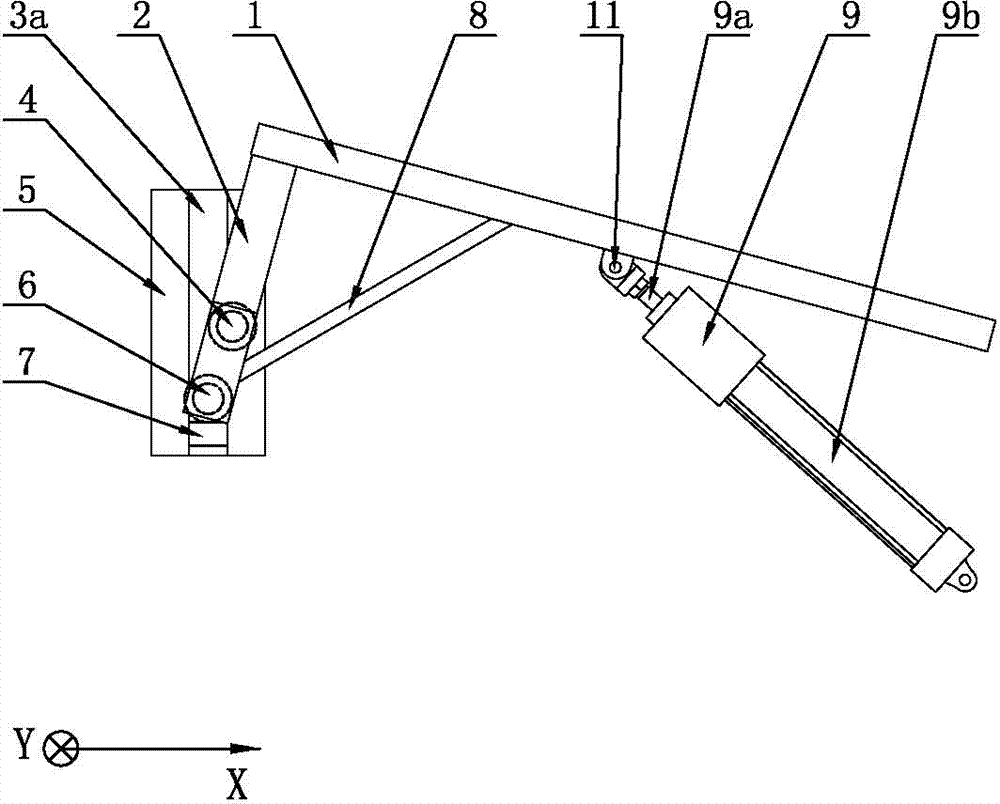
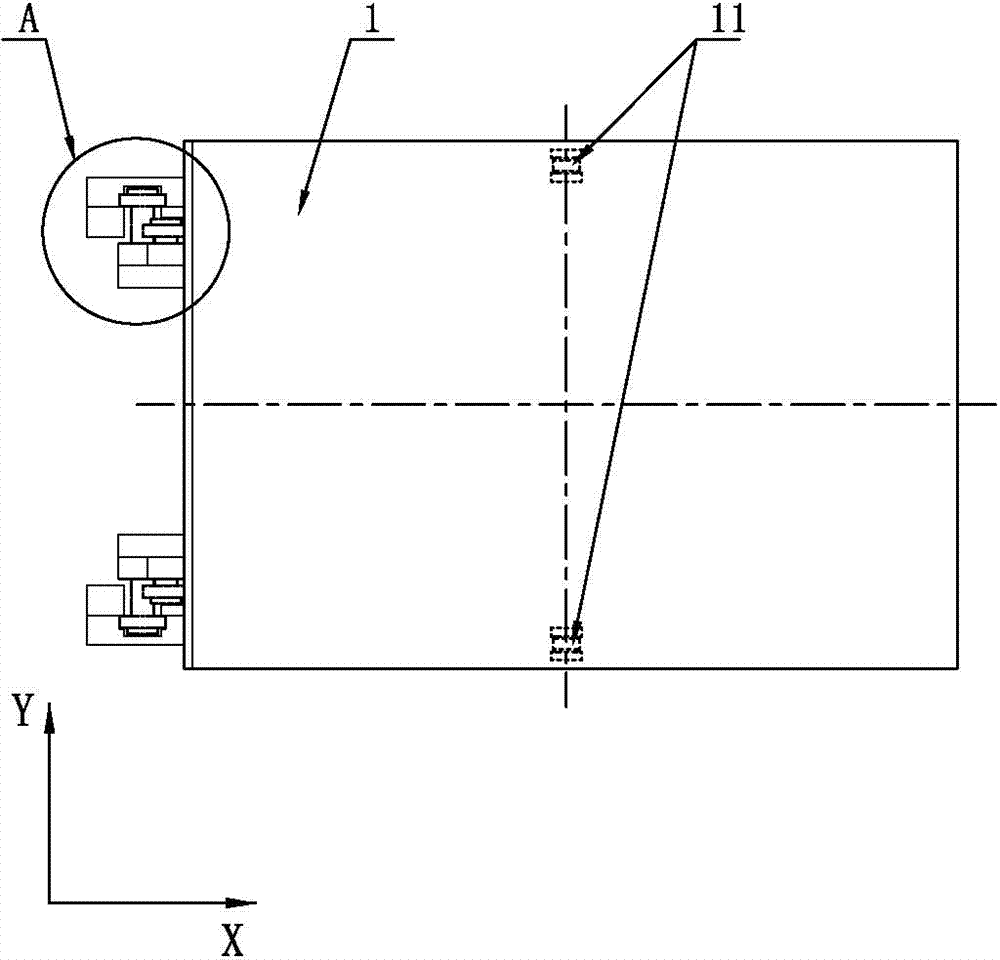
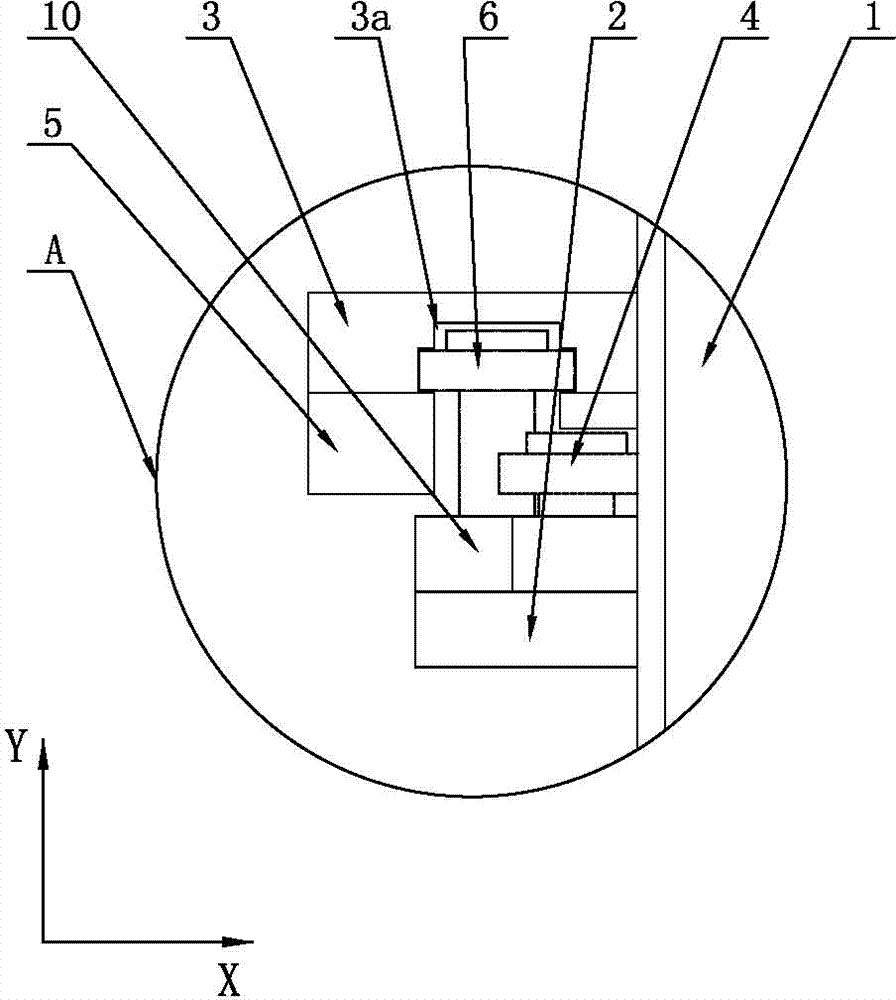
[0015] Such as Figure 1-3 The shown one kind of plate shearing machine receiving and lifting pallet frame includes two guide rods 2 fixedly installed on the pallet 1, connecting ribs 8 are fixed between the pallet 1 and the guide rod 2, and the guide rod 2 passes through the guide bearing 6 Slidingly set in the guide groove 3a on the guide seat 3, the guide seat 3 is installed on the base, the limit block 7 is arranged at the bottom of the guide groove 3a, the limit baffle plate 5 is also arranged on the guide seat 3, and the guide rod 2 is also provided with There is a limit bearing 4 matched with the limit baffle 5, the guide bearing 6 and the limit bearing 4 are all fixedly installed on the guide rod 2 through the connecting block 10, and the bottom of the supporting plate 1 is hinged with two cylinder piston rods 9a, the cylinder 9 and the two hinge points 11 of the pallet 1 are set on the center line of the pallet 1 in the Y direction, and the two hinge points 11 are arr...


PUM


Abstract

The invention discloses a lifting support plate bracket for receiving a material of a steel plate shearer in the field of the steel plate shearer. The lifting support plate bracket comprises two guide rods fixedly arranged on the support plate; the guide rods are arranged in a guide groove on a guide holder in a sliding manner through a guide shaft; a limiting block is arranged at the bottom of the guide groove; a limiting baffle plate is also arranged on the guide holder; a limiting bearing matched with the limiting baffle plate is also arranged on each guide rod; a cylinder piston rod is hinged at the bottom of the support plate; the gravity center of a mechanism composed of the support plate and the guide rods is positioned between a hinge point on the support plate and the guide bearing, and a cylinder drum is hinged on the base. According to the lifting support plate bracket, the material receiving work of a board is finished by two cylinders matched with the guide bearing and a limiting bearing to control the support plate to act and rotate up and down; the material receiving control process is more convenient and reliable; the failure rate is reduced; the production cost is reduced, and the lifting support plate bracket can be applied to the material receiving process of the steel plate shearer at the same time.

Description

technical field [0001] The invention relates to a shearing machine, in particular to a material receiving device of the shearing machine. Background technique [0002] In the working process of the shearing machine in the prior art, if the processed plate is not collected by the receiving mechanism, the processed material will directly fall on the ground, so that it is easy to clean the corners of the processed plate. cause damage, and now it is generally achieved by installing a receiving mechanism for the shearing machine to realize the collection of the plates. The receiving mechanism in the prior art includes a receiving plate, and the piston rods of the cylinders are respectively installed on the four corners of the bottom of the receiving plate. , during work, first raise the receiving plate, when the processed plate falls into the receiving plate, control the four cylinders to drive the receiving plate down at the same time, when it falls to a certain position, stop t...

Claims


Application Information

Patent Timeline
IPC IPC(8): B21D43/28
Inventor 严伟
Owner 扬州恒佳机械有限公司
Why Eureka
Try Eureka