Drill bit

一种钻头、切削刃的技术,应用在修钻、阶梯钻、麻花钻等方向,达到稳定切削的效果

Active Publication Date: 2012-12-19
SUBARU CORP
View PDF8 Cites 7 Cited by
  • Summary
  • Abstract
  • Description
  • Claims
  • Application Information

AI Technical Summary

Problems solved by technology

However, for example, at the manufacturing site of a structure using the above-mentioned components in the aircraft manufacturing industry, etc., due to the structure of the structure or the positional relationship with the surrounding components, etc., there are many situations where it is impossible to choose which side of the surface to perforate, so it is necessary to A drill that can pierce well on either side

Method used


Image

  • Drill bit
  • Drill bit
  • Drill bit

Examples


Embodiment Construction

[0071] Hereinafter, an embodiment of the present invention will be described with reference to the drawings. The following is an embodiment of the present invention, but does not limit the present invention.

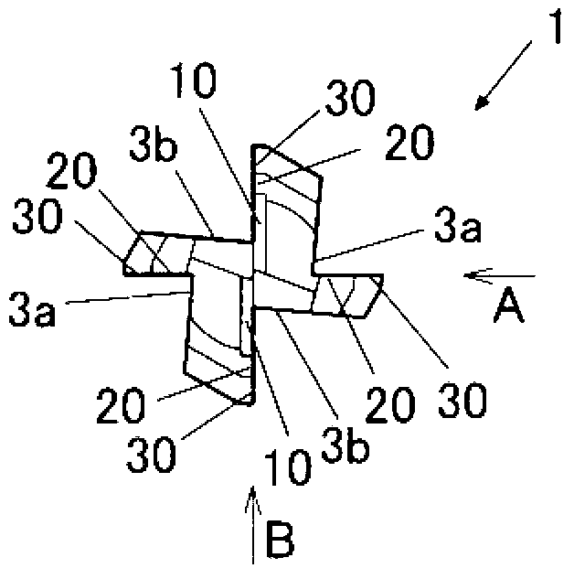
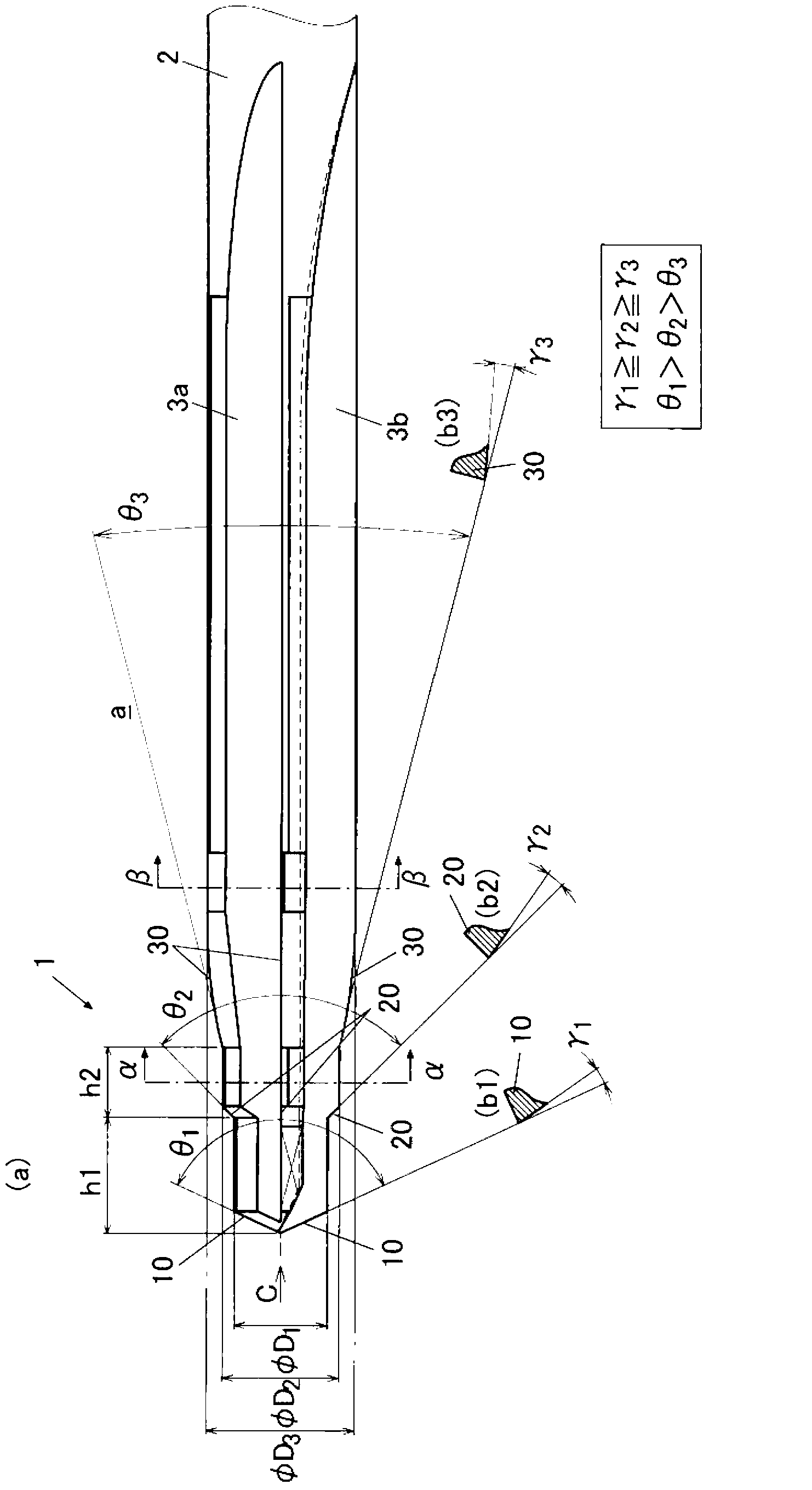
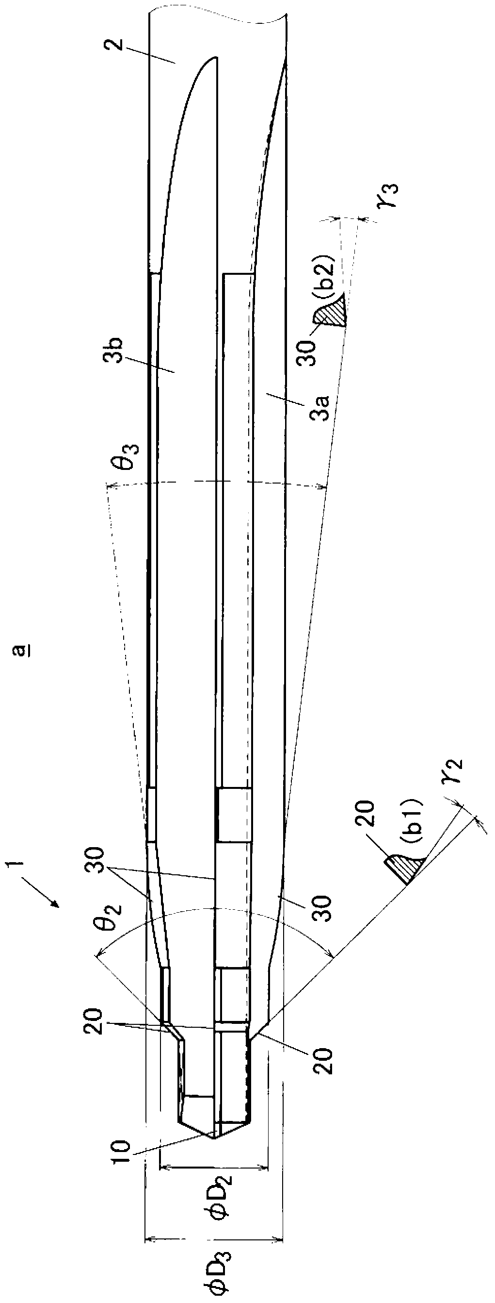
[0072] Such as figure 1 , figure 2 and image 3 As shown, the drill a of this embodiment has a chisel portion 1 and a shank portion 2 . Four straight V grooves 3 a , 3 b , 3 a , 3 b are formed from the chisel blade 1 to the shank 2 .

[0073] The drill a of the present embodiment has three stages of cutting edges 10 , 20 , and 30 divided in the axial direction.

[0074] The first-stage cutting edge 10 is two cutting edges arranged at a distance of 180 degrees from each other around the drill axis, formed from the front end of the drill, and has a maximum diameter φD 1 .

[0075] The second segment cutting edge 20 is 4 cutting edges arranged at different positions every 90 degrees around the drill bit axis, separated by a distance h1 from the drill bit front end t...


PUM


Abstract

Provided is a drill bit which can perform punching long-term and stably in a process of performing punching on a to-be-cut material which is stacked by a metal component and a fiber reinforced resin composite layer.The drill bit includes at least two stepped cutting edges a which are axially split. A cutting edge of a first step from a tip is formed so as to satisfy at least one of the following conditions. That is, a number of blades is smaller, a point angle of the cutting edge is larger, or a clearance angle of the cutting edge is larger than that of cutting edges of a second and subsequent step(s). As a result, a thrust resistance during a perforation can be reduced compared with a case in which the first step cutting edge is formed such that the number of blades, the point angle of the cutting edge and the clearance angle of the cutting edge are the same as those of the second and subsequent step(s). For example, under a condition of using two blades of the first step cutting edge, four blades of the second step cutting edge, four blades of a third step cutting edge, and the point angles [theta]1)[theta]2)[theta]3, and the clearance angles [gamma]1>=[gamma]2>=[gamma]3, each point angle of the first step cutting edge and the second step cutting edge is constant, and the point angle of the third step cutting edge gradually reduces as moving towards a rear end of the drill bit, so that ridge of the cutting edges forms a smooth curve shape.

Description

technical field [0001] The invention relates to a drill bit whose cutting edge is divided into steps in the axial direction. Background technique [0002] As known, a drill bit is used as the piercing tool. A 2-flute drill is widely used (for example, Patent Document 1). [0003] Existing typical drill bits such as Figure 10 and Figure 11 As shown in the drill b shown, the front end has two cutting edges with a constant rake angle. [0004] On the other hand, in various industries, it is required to perforate a workpiece W of Figure 10 and Figure 11 The metal part W1 and the resin composite material W2 shown are laminated|stacked. This is because the fiber-reinforced resin composite material is used to achieve weight reduction, and a metal surface is arranged on the inner surface or the outer surface, and bolts and other connecting members are inserted into the holes provided in the two parts. Efficient and high-precision perforation operations. An example of the m...

Claims


Application Information

Patent Timeline
Patent Type & Authority Applications(China)
IPC IPC(8): B23B51/00
CPCB23B51/009B23B2222/04B23B2251/18B23B2251/04B23B2222/88B23B2226/275B23B2251/204B23B2251/14Y10T408/905Y10T408/906Y10T408/9065B23B51/02B23B51/08
Inventor 东胁启文桥本英二斋藤学渡边政雄中畑达雄
Owner SUBARU CORP
Why Eureka
Try Eureka