
an electric valve

An electric valve and valve seat technology, applied in the direction of lift valve, valve details, valve device, etc., can solve the problems of inability to balance in time, increase the size of the motor, and disadvantage the miniaturization of the valve body, and achieve the advantages of miniaturization design and reduction. Small axial resistance, the effect of reducing the differential pressure

Active Publication Date: 2017-02-22
ZHEJIANG SANHUA CLIMATE & APPLIANCE CONTROLS GRP CO LTD
View PDF12 Cites 0 Cited by
  • Summary
  • Abstract
  • Description
  • Claims
  • Application Information

AI Technical Summary

Problems solved by technology

[0007] Due to the large diameter of the valve port of the electric valve, when the valve core is slightly lifted away from the valve port, the pressure at the lower end of the valve core guide section drops rapidly. Since the valve core guide section cooperates with the valve seat core in a small gap, there is throttling at this time, which cannot Timely balance will lead to the formation of pressure difference between the upper and lower sides of the guide section of the spool, which is the main cause of the axial resistance of the spool. In order to overcome the axial resistance of the spool and lift the spool to open the valve port smoothly, it is necessary to increase the size of the motor. Conducive to the miniaturization of the valve body

Method used


Image

  • an electric valve
  • an electric valve
  • an electric valve

Examples


Embodiment Construction

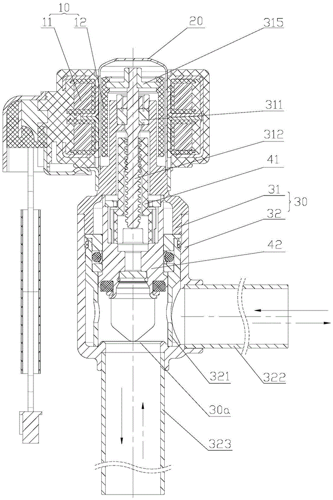
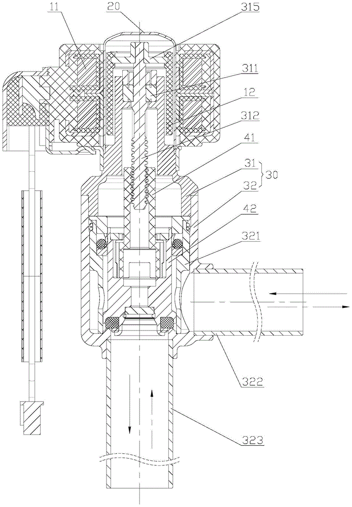
[0037] The core of the present invention is to provide an electric valve, which has small axial resistance to the lifting of the valve core and high valve opening capability, thereby reducing the size of the motor and facilitating the miniaturization of the valve body.

[0038] In order to enable those skilled in the art to better understand the solution of the present invention, the present invention will be further described in detail below in conjunction with the accompanying drawings and specific embodiments.

[0039] What needs to be explained here is that the upper and lower localizers involved in this article are based on Figure 1 to Figure 13 The components are located in the drawings and the positions of the components are defined only for the clarity and convenience of expressing the technical solution. It should be understood that the orientation words used herein shall not limit the scope of protection claimed in this application.

[0040] Please refer to Figur...


PUM


Abstract

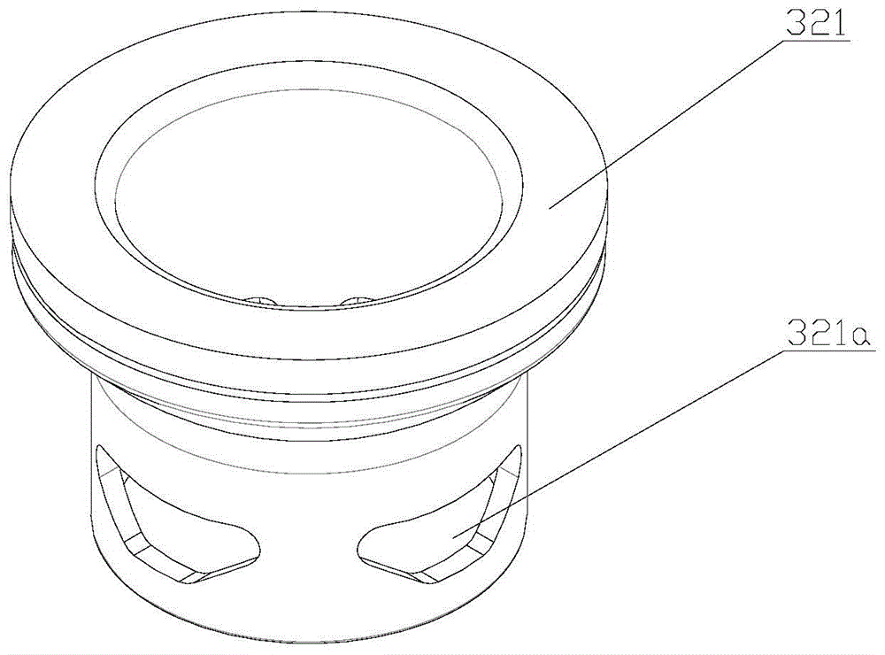
The invention discloses an electric valve. The electric valve comprises a valve base, a valve base core and a valve core, wherein the valve base core is fixed in an inner cavity of the valve base, and is provided with a flow adjusting groove in the peripheral wall; the valve core is arranged in a core cavity of the valve base core; the lower end of the valve core has a guide section greater than a valve core body in diameter; the guide section is in clearance fit with the valve base core; and the ratio of the area of a throttle channel between the guide section and the valve base core to the circulating area of a valve port of the valve base is 1.5-9%. When the valve core is slightly deviated from the valve port, the balance of upper and lower pressure of the guide section of the valve core is helpful to be accelerated, so that the difference of upper and lower pressure of the guide section of the valve core is reduced, the pressure different force suffered by the guide section of the valve core is reduced, the axial resistance of the valve core is reduced, the valve core is convenient to be lifted, the increment of the motor size caused by overcoming greater axial resistance on the valve core can be prevented, and the miniaturization of the valve body is facilitated.

Description

technical field [0001] The invention relates to the technical field of fluid control components, in particular to an electric valve. Background technique [0002] In air conditioners, refrigerators, heat pump water heaters and various refrigeration and heating equipment, or other occasions that need to regulate fluid flow, flow regulating valves are usually used, and electric valves are one of the flow regulating valves. [0003] The electric valve usually includes a valve seat, which is provided with a valve port, a first port and a second port, and the opening and closing of the valve port controls the connection or disconnection of the first port and the second port; the valve seat is provided with a valve seat The core, the peripheral wall of the valve seat core is provided with a flow regulating groove, and the flow rate of the fluid circulating between the first interface and the second interface can be adjusted through the opening of the flow regulating groove. [00...

Claims


Application Information

Patent Timeline
Patent Type & Authority Patents(China)
IPC IPC(8): F16K1/02F16K1/36F16K1/42
CPCF16K1/02F16K1/36F16K1/42F16K47/04
Inventor 不公告发明人
Owner ZHEJIANG SANHUA CLIMATE & APPLIANCE CONTROLS GRP CO LTD
Learn More