
Wear-resistant clamp plate device of stuffing box crimping machine

A technology of crimping machine and stuffing box, which is used in mechanical equipment, friction-clamped detachable fasteners, textiles and papermaking, etc. Can not achieve timely automatic compensation and other problems, to achieve the effect of simple processing and installation

Active Publication Date: 2012-12-19
NANTONG CELLULOSE FIBERS CO LTD
View PDF6 Cites 4 Cited by
  • Summary
  • Abstract
  • Description
  • Claims
  • Application Information

AI Technical Summary

Problems solved by technology

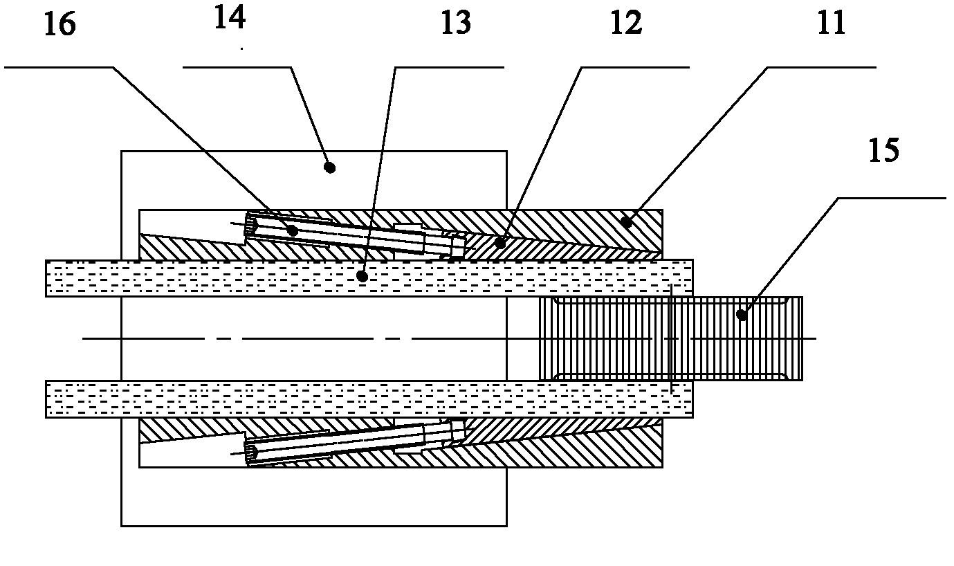
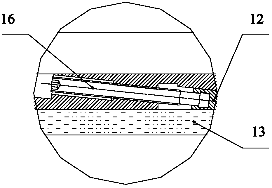
The clamping force of the wear-resistant splint 13 and the side of the curling roller 15 depends on the screw 16 screwing in and out to drive the wedge-shaped adjustment block 12 to slide relative to the bracket 11, and the wedge-shaped body of the adjustment block 12 pushes the wear-resistant splint 13 It is closely attached to the side of the curling roller 15, and the clamping force between the wear-resistant splint 13 and the side of the curling roller 15 is difficult to accurately adjust to the set value
When the machine is running, due to the long-term sliding friction between the high-speed rotating curling pair roller 15 and the stationary wear-resistant splint 13, the wear-resistant splint 13 or the side of the curling roller 15 is mechanically worn, and the wear-resistant splint 13 or curling pair There will be a gap between the sides of the rollers 15, and the material will be curled and squeezed into the gap by the rollers 15, causing damage and affecting product quality.
The gap caused by mechanical wear is a continuous and gradually increasing process. The existing structure cannot realize automatic compensation in time and can only be manually adjusted intermittently; the patent ZL200320110083.7 related to this field proposes to The joint surface between the wedge-shaped adjustment block and the support is designed from a plane joint to a cylindrical joint; thereby solving the problem of parallelism adjustment between the wear-resistant splint and the side of the curling roller, so that the wear-resistant splint and the side of the curling roller can be fully fitted; The patent ZL200320110083.7 adopts the adjustment screw structure to realize the adjustment of the side clamping force of the wear-resistant splint and the curling roller

Method used


Image

  • Wear-resistant clamp plate device of stuffing box crimping machine
  • Wear-resistant clamp plate device of stuffing box crimping machine
  • Wear-resistant clamp plate device of stuffing box crimping machine

Examples


Embodiment 1

[0025] Such as Figure 4 As shown, a stuffing box crimping machine wear-resistant splint adjustment device includes a bracket 1, a relatively sliding adjustment block 2 is installed on the bracket 1, a wear-resistant splint 3 is installed on the inside of the adjustment block 2, two identical brackets 1, and the adjustment block 2. The wear-resistant splint 3 is symmetrically installed on both sides of the curling roller 5 . The adjustment block 2 is provided with a stepped part, one end of the stepped part is a cylindrical piston with a smaller diameter, and the cylindrical piston can slide back and forth along the cylinder axis in the cylinder of the bracket, and the other end of the stepped part is a cylindrical piston with a larger diameter The wedge-shaped body, the cylindrical piston and the wedge-shaped body are processed into one piece or assembled together after segmental processing; the surface of the wedge-shaped body is composed of multiple planes, and is composed ...

Embodiment 2

[0027] Such as Figure 5As shown, a stuffing box crimping machine wear-resistant splint adjustment device includes a bracket 1, a relatively sliding adjustment block 2 is installed on the bracket 1, a wear-resistant splint 3 is installed on the inside of the adjustment block 2, two identical brackets 1, and the adjustment block 2. The wear-resistant splint 3 is symmetrically installed on both sides of the curling roller 5 . The adjustment block 2 is provided with a stepped portion, one end of the stepped portion is a first cylindrical piston with a smaller diameter, the first cylindrical piston can slide back and forth in the cylinder of the bracket along the cylinder axis, the other end of the stepped portion is a diameter opposite The larger wedge body of the first cylindrical piston, the first cylindrical piston and the wedge body are processed as a whole or assembled together after segmental processing; the surface of the wedge body is composed of multiple planes, which is...


PUM


Abstract

The invention discloses a wear-resistant clamp plate device of a stuffing box crimping machine. The wear-resistant clamp plate device comprises brackets, adjusting mechanisms, wear-resistant clamp plates, a base and paired crimping rollers; the adjusting mechanisms capable of relatively sliding are arranged on the brackets; the wear-resistant clamp plates are arranged at the inner sides of the adjusting mechanisms; the two same brackets, the two adjusting mechanisms and the two wear-resistant clamp plates are symmetrically mounted at two sides of the paired crimping rollers and arranged on the base; the wear-resistant clamp plate device further comprises a fluid thrust device; a fluid inlet and a cylinder body are arranged on each bracket; one end of each adjusting mechanism extends into the cylinder body and cooperates with the cylinder body; and the fluid of the fluid thrust device enters the cylinder body from the fluid inlet and drives the wear-resistant clamp plates to move in the direction close to the side of the paired crimping rollers by means of the adjusting mechanisms. The fluid thrust device can be realized by liquid or gas. The device provided by the invention not only can conveniently and accurately adjust the clamping force of the wear-resistant clamp plates and both sides of the paired crimping rollers to be a preset value, but also can automatically compensate the mechanical wear of of the wear-resistant clamp plates or both sides of the paired crimping rollers, generated in the running of the machine, and can keep the preset clamping force all along.

Description

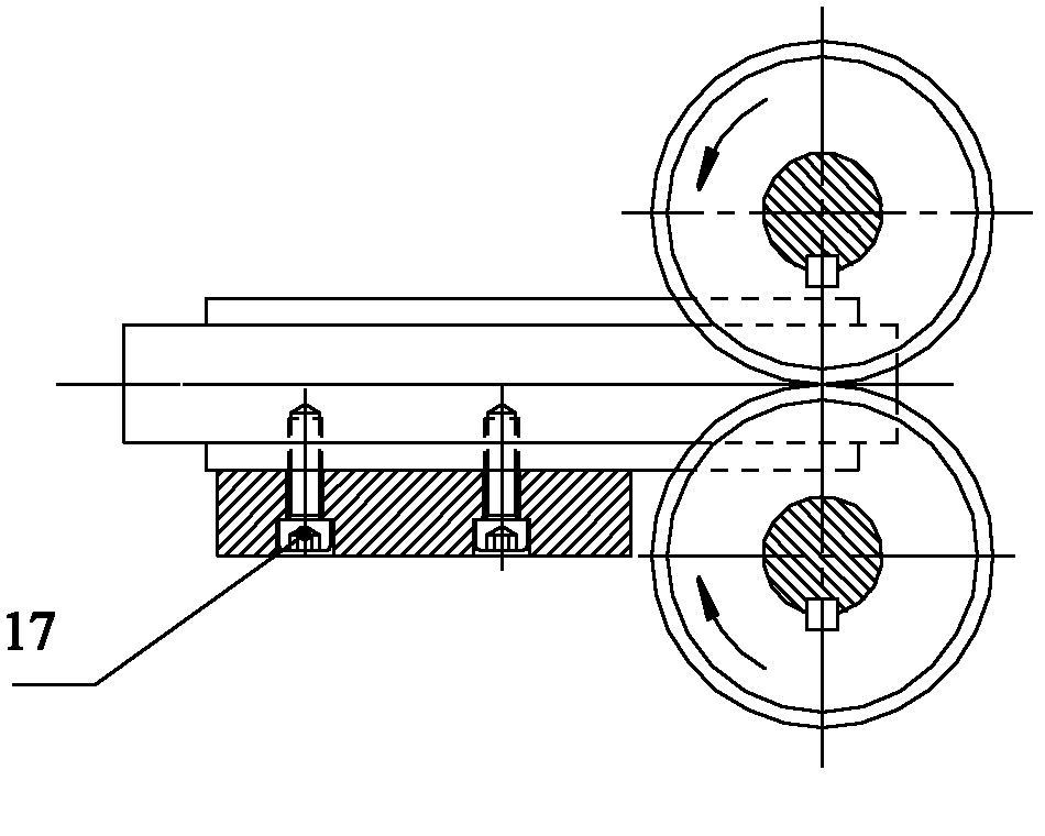
technical field [0001] The invention belongs to the field of crimping devices, and relates to a wear-resistant splint adjusting device of a stuffer box crimping machine. Background technique [0002] At present, the wear-resistant splint adjustment device of the known stuffer box crimping machine is installed on the fixed base 14 with a screw 17, and a pair of wear-resistant splints 13 are widely used to be contained on both sides of the crimping pair roller 15, so that the wear-resistant splint 13 and the curling pair The clamping force on the side of the roller 15 is kept at an appropriate set value, which not only prevents the material from being extruded from the edge of the curled roller 15, but also minimizes the friction between the wear-resistant splint 13 and the side of the curled roller 15 . The clamping force of the wear-resistant splint 13 and the side of the curling roller 15 depends on the screw 16 screwing in and out to drive the wedge-shaped adjustment bloc...

Claims


Application Information

Patent Timeline
Patent Type & Authority Applications(China)
IPC IPC(8): D02G1/12
CPCD02G1/12F16B2/14
Inventor 杨宝如曹建华
Owner NANTONG CELLULOSE FIBERS CO LTD
Learn More