Energy-saving fan

A fan and body technology, applied in the field of energy-saving fans, can solve the problems of inconvenient installation and use, large power consumption, high noise, etc., and achieve the effects of convenient maintenance and replacement, easy installation and maintenance, and low power consumption.

Active Publication Date: 2014-12-10
高通环保科技股份有限公司
View PDF6 Cites 0 Cited by
  • Summary
  • Abstract
  • Description
  • Claims
  • Application Information

AI Technical Summary

Problems solved by technology

In limited spaces, such as tunnels or underground garages, due to the limitation of space, it is impossible to arrange fans with large impellers, and only multiple fans with smaller impellers can be used to achieve ventilation and ventilation, which is not only inconvenient to install and use, but also consumes large battery
The existing fan still has the disadvantages of high noise and poor anti-seismic effect

Method used


Image

  • Energy-saving fan
  • Energy-saving fan

Examples


Embodiment 1

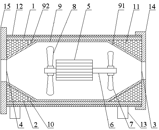
[0031] Such as figure 1 As shown, the energy-saving fan, which includes:

[0032] Housing 1, housing 1 has an air channel 2 for air to pass through, the cross section of the air channel 2 is circular, and the two axial ends of the air channel 2 are respectively provided with an air suction port 3 and an air discharge port 4, In order to increase the air volume and wind pressure, the air suction port 3 and the air discharge port 4 are arranged in a circular shape, and the diameter ratio of the air suction port 3 and the air discharge port 4 is set to 1:1.2.

[0033] The energy-saving fan also includes a motor 5, the motor 5 is arranged in the housing 1, the rotating shaft 6 of the motor 5 extends out from the front and rear ends of the motor 5, so that the front and rear ends of the motor 5 can be connected to the load at the same time, and the rotating shaft 6 is located in the air passage 2 in the direction of the axis. The front impeller 7 is fixed on the rotating shaft 6,...

Embodiment 2

[0043] In this embodiment, the front impeller 7 adopts a T30 impeller with a machine number of 6, the rear impeller 8 adopts a T35 impeller with a machine number of 6.3, and the angle between the front end 91 and the rear end 92 and the inner surface of the housing 1 is 35° , The soft filler 11 is fire-resistant silica gel, the shock-resistant and sound-absorbing layer 12 is composed of sound-absorbing cotton, and the rest of the technical features are the same as in Example 1.

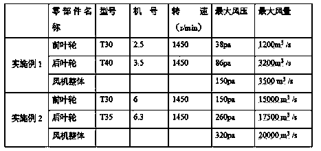
[0044] The following table shows the maximum wind pressure and maximum air volume of the impellers used in Embodiments 1 and 2, and the maximum wind pressure and maximum air volume of the energy-saving fans in Embodiments 1-3.

[0045]

[0046] As can be seen from the above table, the maximum wind pressure and maximum air volume of the present invention are greater than the maximum wind pressure and maximum air volume of a single impeller.

[0047] Compared with the traditional fans, the present i...


PUM


Abstract

The invention discloses an energy-saving fan, which comprises a shell (1), and a motor (4), a front impeller (7) and a rear impeller (8), which are arranged inside the shell (1), wherein the front impeller (7) and the rear impeller (8) are installed on a rotating shaft (6) of the motor (4), and the flow rate and the wind pressure of the front impeller (7) are smaller than that of the rear impeller (8) under the same rotation speed. Through the rotation of the front impeller (7) and the rear impeller (8), airflow is formed, the air has large air quantity and large air pressure, so that the energy-saving fan has characteristics of an axial flow fan and a centrifugal fan; and moreover, the size is small, the energy consumption is low, and the vibration and noise also can be reduced.

Description

technical field [0001] The invention relates to the technical field of fans, in particular to an energy-saving fan. Background technique [0002] Fans are used in the fields of exhaust, air supply and dust removal. In the traditional fan technical field, the fan only uses one impeller, and the impeller is fixed on the motor shaft. Air enters the inside of the fan from the air inlet, is driven by the impeller to obtain kinetic energy, and forms a high-speed airflow to flow out from the air outlet. Among them, the larger the diameter of the impeller, the higher the speed, the greater the kinetic energy obtained by the airflow, and the higher the wind pressure and air volume. In limited spaces, such as tunnels or underground garages, due to the limitation of space, it is impossible to arrange fans with large impellers, and only multiple fans with smaller impellers can be used to achieve ventilation and ventilation, which is not only inconvenient to install and use, but also c...

Claims


Application Information

Patent Timeline
Patent Type & Authority Patents(China)
IPC IPC(8): F04D25/08F04D29/52F04D29/66
Inventor 胡登燕
Owner 高通环保科技股份有限公司
Why Eureka
Try Eureka