
High flow check valve for filter

A large-flow, one-way valve technology, applied in fluid pressure actuation devices, fluid pressure actuation system components, mechanical equipment, etc., can solve pollution and other problems

Active Publication Date: 2016-06-22
SOLINER NANJING INTELLIGENT TECH CO LTD
View PDF6 Cites 0 Cited by
  • Summary
  • Abstract
  • Description
  • Claims
  • Application Information

AI Technical Summary

Problems solved by technology

[0003] The purpose of the present invention is to solve the problem of oil pollution and improve the reliability of the system by developing a large-flow one-way valve for filters with a novel structure, which can be used in combination with the oil return filter for the defects of the above-mentioned system

Method used


Image

  • High flow check valve for filter

Examples


Embodiment Construction

[0012] The present invention will be further described below in conjunction with accompanying drawing:

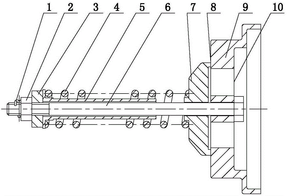
[0013] Such as figure 1 As shown, the present invention includes a valve body 9 connected to the oil return filter, one side of the valve body 9 is provided with an oil inlet 10, and the other side is provided with an oil outlet 8. A cover plate 7 is installed on the oil outlet 8, and a bolt 6 is installed at the center of the cover plate 7, and a pressing plate 7, a support pipe 5 and a spring 4 are set on the bolt 6. One end of the support tube 5 is located inside the spring 4 , and the other end is connected to the pressing plate 7 . The support tube 5 plays the role of supporting spring and fixing position. One end of the spring 4 bears on the cover plate 7 , and the other end is connected to the pressing plate 3 . Also installed on the bolt 6 is located on the outside of the pressure plate 3 (ie figure 1 The locknut 2 on the left side of the shown pressure plate 3)...


PUM


Abstract

The invention discloses a large-flow check valve for a filter. A valve body (9) is connected with an oil return filter, a cover plate (7), a support pipe (5), a spring (4) and a pressure plate (3) are installed in the valve body (9) and stringed together by a bolt (6), opening pressure is fixed and regulated by a locknut (2), and an opening pin (1) is also installed at the end of the bolt (6) so as to prevent the bolt (6) from dropping. With the adoption of the large-flow check valve, the structure is novel and practical, pressure drop of a flow is small, oil passing capability is strong, and the requirements for adding the oil return filter of an engineering machinery hydraulic system can be satisfied.

Description

technical field [0001] The invention relates to an oil return filter system in a construction machine hydraulic system, in particular to a one-way valve. Background technique [0002] The flow of hydraulic oil in the hydraulic system of construction machinery depends on the displacement of the pump, the number of engine revolutions and the area ratio at both ends of the oil cylinder. Since the number of engine revolutions varies with the operation and changes greatly (1000 rpm to 2500 rpm) and the oil cylinder The area ratio at both ends is large, so the flow rate changes greatly, so it is not easy to choose an oil return filter, because the flow rate changes greatly, and the filter should be selected according to the maximum flow rate when installing the filter, the installation space will be large, it cannot be installed, and the cost is high . The one-way valve is used with the filter at the same time and connected in parallel. At present, many manufacturers do not insta...

Claims


Application Information

Patent Timeline
Patent Type & Authority Patents(China)
IPC IPC(8): F15B21/04
Inventor 黄翔周国贞王德达杨芝刚周国龙冷云
Owner SOLINER NANJING INTELLIGENT TECH CO LTD
Learn More