High-temperature discharging valve

A discharge valve, high temperature technology, applied in the valve details, valve device, valve shell structure and other directions, can solve the temperature use range and use occasion restrictions, plastic sealing ring erosion or scratches, discharge valve performance degradation, etc. problems, to protect the performance and life, prevent leakage, and improve the effect of heat dissipation

Inactive Publication Date: 2012-12-19
FUJIAN FEIDA VALVE TECH CO LTD
View PDF8 Cites 4 Cited by
  • Summary
  • Abstract
  • Description
  • Claims
  • Application Information

AI Technical Summary

Problems solved by technology

In order to achieve good sealing performance of conventional unloading valves, most of the sealing materials are plastic soft seals. This type of soft seal unloading valve can only be used under normal temperature conditions, and the plastic sealing ring itself is very vulnerable to damage from the pipeline. The erosion or scratching of the flowing medium reduces the sealing effect or completely loses the sealing performance. Poor heat dissipation performance and untimely heat dissipation lead to structural damage, which greatly reduces the performance of the unloading valve

Method used


Image

  • High-temperature discharging valve
  • High-temperature discharging valve
  • High-temperature discharging valve

Examples


Embodiment Construction

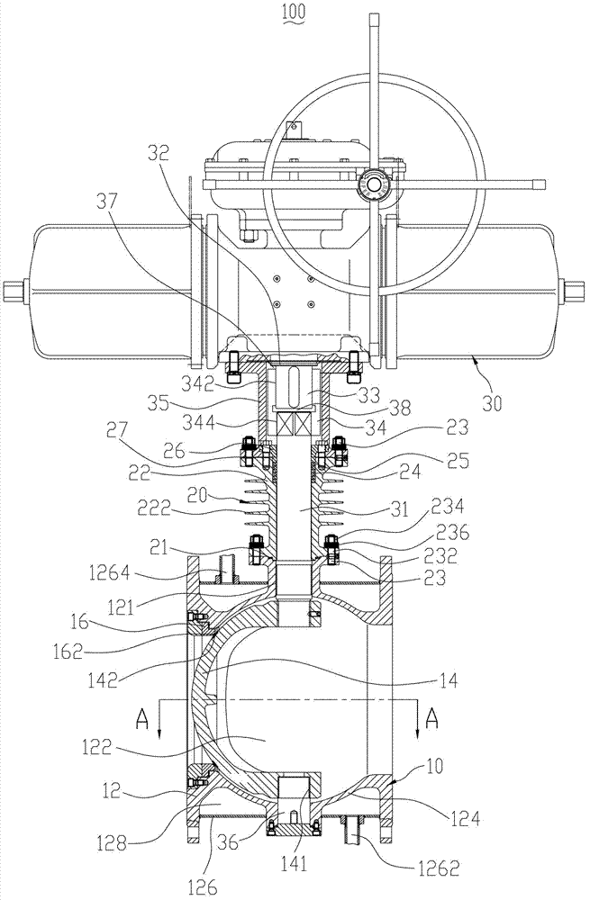
[0044] Please check figure 1 , a high-temperature unloading valve 100 of the present invention, comprising: a valve body part 10 for allowing high-temperature medium to circulate or block flow, a heat dissipation part 20 for dissipating heat, and a valve body part 10 for driving the action Drive part 30. The driving part 30 , the heat dissipation part 20 , and the valve body part 10 are arranged sequentially from top to bottom.

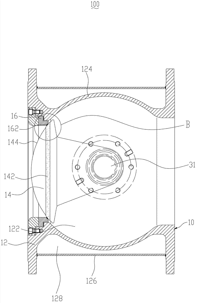
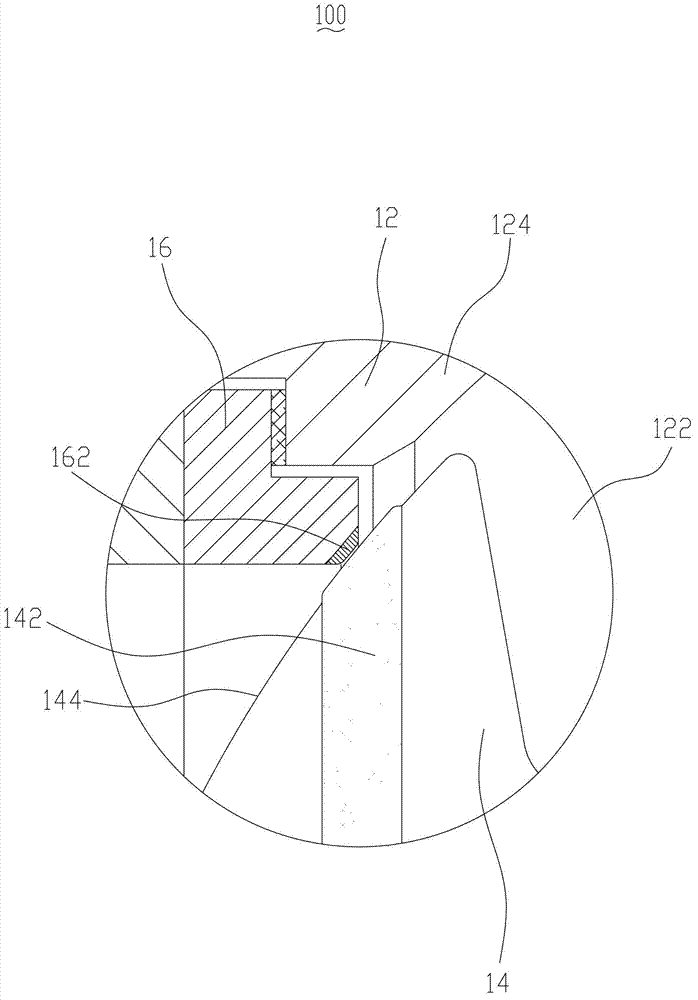
[0045] Please refer to figure 1 and figure 2, the valve body part 10 includes a valve body 12 , a hemispherical body 14 and a valve seat 16 . A channel 122 is transversely penetrating through the middle of the valve body 12 , and the medium flows through the channel 122 from left to right. The valve body 12 includes a sidewall 124 and a cooling jacket 126 disposed along the entire circumference. The sidewall 124 surrounds the channel 122 . The cooling jacket 126 is located outside the sidewall 124 . The cooling jacket 126 and the side wall 124...


PUM


Abstract

The invention discloses a high-temperature discharging valve which comprises a valve body part, a driving part and a radiating part, wherein the valve body part is used for circulating or stopping a high-temperature medium; the valve body part comprises a valve body and a hemispheroid; a runner is arranged on the middle part of the valve body; the hemispheroid can rotate relative to the valve body in the valve body and can selectively seal or open the runner; the driving part is used for driving the hemispheroid to rotate; the driving part comprises an upper valve rod which synchronously rotates with the hemispheroid; one end of the upper valve rod passes through the valve body and is connected with the hemispheroid; the radiating part comprises a radiating bracket, a filler and an end cover; the radiating bracket is sleeved on the upper valve rod; one end of the radiating bracket is in sealing connection with the valve body; the filler is arranged in a sealing space between the radiating bracket and the upper valve rod; and the filler is tightly pressed by the end cover from the other end of the radiating bracket. The heat transferred by the valve body is quickly radiated by the radiating bracket, so that the use performance and the service life of the upper valve rod and the whole driving part are protected, and the high-temperature discharging valve has the advantage of excellent heat radiating property.

Description

technical field [0001] The invention relates to a high temperature unloading valve. Background technique [0002] The unloading valve is a device widely used in petroleum, chemical, natural gas and other industries to control the circulation, closure, regulation and other functions of the medium on the pipeline. In order to achieve good sealing performance of conventional unloading valves, most of the sealing materials are plastic soft seals. This type of soft seal unloading valve can only be used under normal temperature conditions, and the plastic sealing ring itself is easily damaged by the pipeline. The erosion or scratching of the flowing medium reduces the sealing effect or completely loses the sealing performance. Poor heat dissipation performance and untimely heat dissipation lead to structural damage, which greatly reduces the performance of the unloading valve. Contents of the invention [0003] The invention provides a high-temperature unloading valve with goo...

Claims


Application Information

Patent Timeline
Patent Type & Authority Applications(China)
IPC IPC(8): F16K5/06F16K49/00F16K41/02F16K27/06F16K5/08
Inventor 庄学彬温国辉戴志坚
Owner FUJIAN FEIDA VALVE TECH CO LTD
Why Eureka
Try Eureka