
Force feedback button device and click device employing the device

A force feedback and button technology, which is applied in the field of feedback button devices with a sense of frustration, can solve the problems of shortening switch life, switch failure, and inability to meet customer preferences at the same time, and achieves the effect of avoiding mechanical wear and prolonging service life.

Active Publication Date: 2012-12-19
G TECH TECH
View PDF4 Cites 23 Cited by
  • Summary
  • Abstract
  • Description
  • Claims
  • Application Information

AI Technical Summary

Problems solved by technology

This kind of mechanical rigid contact switch structure, due to the existence of this sudden change, will inevitably cause wear and aging, thereby shortening the life of the switch, and eventually causing the switch to fail
[0005] On the other hand, the release force generated by the reed of the tact switch is determined by fixed factors such as the formation process, material, and installation and fixing method of the reed, so the release force of the switch cannot be adjusted during use. Therefore, it cannot meet the preferences of different occasions in customer applications at the same time

Method used


Image

  • Force feedback button device and click device employing the device
  • Force feedback button device and click device employing the device
  • Force feedback button device and click device employing the device

Examples


Embodiment Construction

[0043] Below in conjunction with accompanying drawing and embodiment the present invention will be further described:

[0044] The force feedback button device of the present invention is suitable for occasions that need to simulate a switch with segmental feedback, and can replace traditional light touch switches, and can be used in such as computer keyboards, mice, game control handles, remote controllers, and even mobile phones, as one of them. use of physical buttons. Of course, it can also be generalized and applied to a wider field of electrical control.

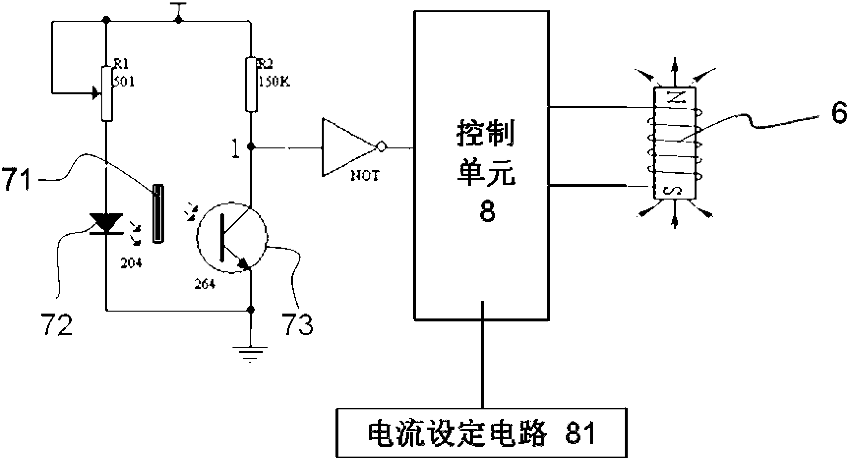
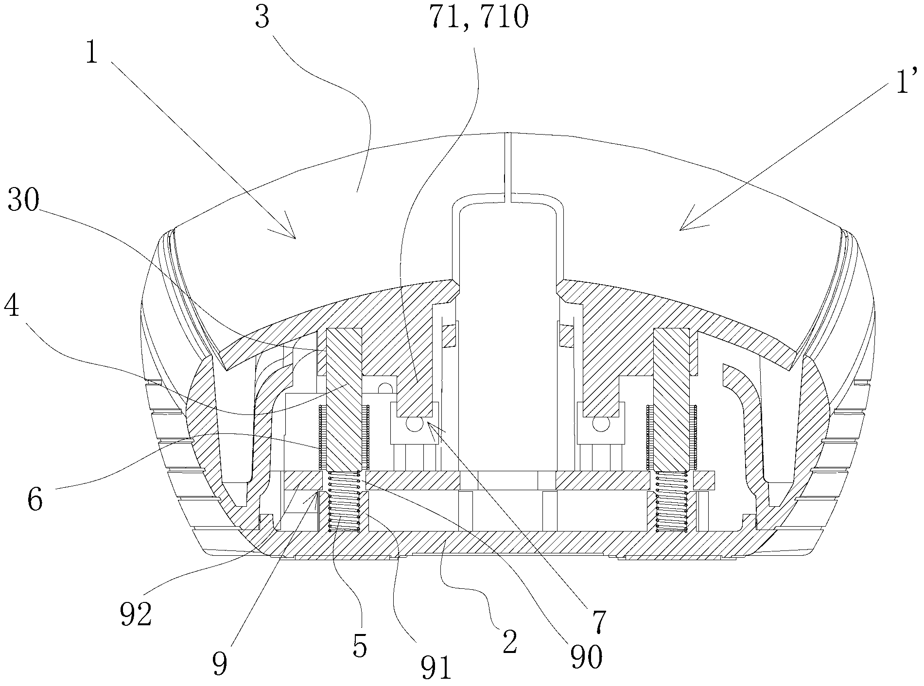
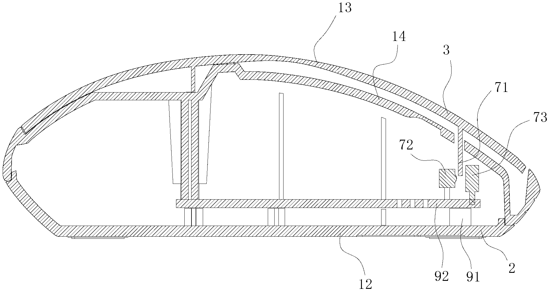
[0045] see figure 1 and figure 2 A structural schematic diagram of the disclosed first embodiment of the force feedback button device of the present invention. In this embodiment, the button devices 1, 1' of the present invention are used in pairs in a pointing device, and the pointing device is a mouse electrically connected to an intelligent terminal such as a computer. The following description will take one of...


PUM


Abstract

The invention discloses a force feedback button device which comprises a base part and a pressing part, wherein the pressing part is arranged above the base part and can operate between the places far away from the base part and close to the base part; the device further comprises a magnetic piece, an electrifying coil, a sensing mechanism and a control unit, wherein two magnetic poles of the magnetic piece face towards the pressing part and the base part respectively; the electrifying coil is provided with a columnar through space into which the magnetic piece is put; the two axial ends of the electrifying coil face towards the pressing part and the base part respectively; one of the magnetic piece and the electrifying coil is linked with the pressing part, and the other one is fixedly arranged with the base part; the sensing mechanism is used for detecting whether the pressing part moves to the place close to the base part and generating corresponding indication signals; the control unit is used for reading the indication signals of the sensing mechanism; when the indication signals represent that the pressing part moves to the place close to the base part, the electrifying coil is powered on through current so as to generate a magnetic field, thereby resulting in the force feedback which is ultimately transmitted to the pressing part. According to the device, the simulation of paragraph feeling is achieved in a non-contact or flexible contact mode, the service life of the button device is prolonged, and the force feedback effect is adjustable, so that the button device is applicable to click devices with physical buttons such as a mouse.

Description

【Technical field】 [0001] The invention relates to the technology related to electrical control keys, in particular to pointing devices with keys such as a mouse and a keyboard for triggering control signals, and in particular to a frustration-feedback key device. 【Background technique】 [0002] The applicant has searched through the patent databases of seven countries and two organizations and found that the buttons of the existing pointing equipment are as large as the control keyboards of household appliances such as refrigerators and televisions, as small as the buttons of the mouse and various controllers, etc., are widely used. The light-touch switch is used as the force-applied object of the input control of the click command. After the tactile switch is pressed, on the one hand, the control action of the finger is converted into an electrical signal and transmitted to the host; is pressed effectively. [0003] The generation of the paragraph feeling of the above-men...

Claims


Application Information

Patent Timeline
IPC IPC(8): H01H13/14H01H13/85
Inventor 黎柏松
Owner G TECH TECH
Learn More