Directional coupler

A directional coupler and electromagnetic coupling technology, applied in waveguide-type devices, electrical components, connecting devices, etc., can solve the problems of increased coupling, power fluctuations, and uneven amplitude characteristics of coupled signals, and achieve a near-flat amplitude characteristic. Effect

Active Publication Date: 2012-12-19
MURATA MFG CO LTD
View PDF4 Cites 30 Cited by
  • Summary
  • Abstract
  • Description
  • Claims
  • Application Information

AI Technical Summary

Problems solved by technology

[0003] However, in the directional coupler described in Patent Document 1, there is a problem that the degree of coupling between the main line and the sub line increases as the frequency of the signal input to the main line increases (that is, t

Method used


Image

  • Directional coupler
  • Directional coupler
  • Directional coupler

Examples


Embodiment approach 1

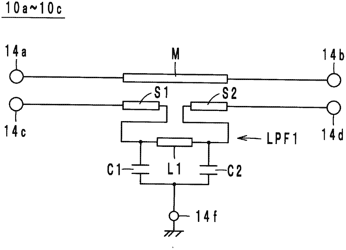
[0023] Next, the directional coupler according to Embodiment 1 will be described with reference to the drawings. figure 1 It is an equivalent circuit diagram of the directional couplers 10 a to 10 c according to Embodiment 1 to Embodiment 3. FIG.

[0024] The circuit configuration of the directional coupler 10a will be described. The directional coupler 10a is used for a predetermined frequency band. For example, when a signal having a frequency band of 824 MHz to 915 MHz (GSM800 / 900) and a signal having a frequency band of 1710 MHz to 1910 MHz (GSM1800 / 1900) are input to the directional coupler 10a, the predetermined frequency refers to 824 MHz to 1910 MHz.

[0025] As a circuit structure, the directional coupler 10a includes external electrodes (terminals) 14a to 14f ( figure 1 The external electrode 14e), the main line M, the sub lines S1, S2, and the low-pass filter LPF1 are not shown. The main line M is connected between the external electrodes 14a, 14b. The sub-line ...

Embodiment approach 2

[0068] Next, the configuration of the directional coupler 10b according to Embodiment 2 will be described with reference to the drawings. Figure 10 It is an exploded perspective view of the laminated body 12b of the directional coupler 10b according to the second embodiment.

[0069] Since the circuit configuration of the directional coupler 10b is the same as that of the directional coupler 10a, description thereof will be omitted. The directional coupler 10b differs from the directional coupler 10a in that, as Figure 10 As shown, the configuration of the main line M, the secondary lines S1, S2, the capacitors C1, C2, and the coil L1. In more detail, in the directional coupler 10a, as Figure 9 As shown, the main line M, sub-lines S1, S2, capacitors C1, C2, and coil L1 are arranged so as to be arranged sequentially from the negative direction side to the positive direction side in the z-axis direction in the above-mentioned order. On the other hand, in the directional co...

Embodiment approach 3

[0072] Next, the configuration of the directional coupler 10 c according to Embodiment 3 will be described with reference to the drawings. Figure 11 It is an exploded perspective view of a laminated body 12c of a directional coupler 10c according to the third embodiment.

[0073] Since the circuit configuration of the directional coupler 10c is the same as that of the directional couplers 10a and 10b, description thereof will be omitted. The directional coupler 10c differs from the directional coupler 10a in the arrangement of the main line M, the sub lines S1, S2, and the low-pass filter LPF1. In more detail, in the directional coupler 10c, as Figure 11 As shown, the main line M, the sub-lines S1, S2, and the low-pass filter LPF1 are arranged along the x-axis direction. Accordingly, in the directional coupler 10c, it is possible to reduce the height of components.


PUM


Abstract

The invention relates to a directional coupler which can make amplitude response of coupling signals in the directional coupler close to flat, and the directional coupler (10a) is used in a predetermined frequency band. A main line (M) is connected between a first terminal (14a) and a second terminal (14b). A first sub line (S1) is connected to a third terminal (14c) and is electromagnetically coupled to the main line. A second sub line (S2) is connected to a fourth terminal (14d) and is electromagnetically coupled to the main line. A low pass filter (LPF1) is connected between the first sub line and the second sub line and causes a phase shift to be generated in a passing signal passing therethrough in such a manner that the phase shift monotonically increases within a range from about 0 to about 180 degrees with increasing frequency in the predetermined frequency band.

Description

technical field [0001] The present invention relates to a directional coupler, in particular to a directional coupler used in wireless communication equipment and the like, and the wireless communication equipment uses high-frequency signals for communication. Background technique [0002] As a conventional directional coupler, for example, a directional coupler described in Patent Document 1 is known. This directional coupler is formed by stacking a plurality of dielectric layers formed with a coiled conductor and a ground conductor. Two coiled conductors are provided. One coil-shaped conductor constitutes the main line, and the other coil-shaped conductor constitutes the sub-line. The main line and the auxiliary line are electromagnetically coupled to each other. In addition, the ground conductor sandwiches the coil-shaped conductor in the stacking direction. Apply ground potential to the ground conductor. In the directional coupler as described above, when a signal i...

Claims


Application Information

Patent Timeline
IPC IPC(8): H01P5/18
CPCH01P5/184
Inventor 田丸育生
Owner MURATA MFG CO LTD
Why Eureka
Try Eureka