Compensation capacitor bank switching method and device

A technology for compensating capacitors and capacitor banks, applied in reactive power compensation, reactive power adjustment/elimination/compensation, etc., can solve problems such as poor reliability of reactive power compensation devices, and achieve extended working life and average trouble-free operation Time, reduce the effect of equipment repair and maintenance costs

Inactive Publication Date: 2015-08-05
LIUZHOU HAIGE ELECTRICAL
View PDF5 Cites 0 Cited by
  • Summary
  • Abstract
  • Description
  • Claims
  • Application Information

AI Technical Summary

Problems solved by technology

[0003] The problem to be solved by the present invention is to provide a compensation capacitor bank switching method and device, which can solve the problem of poor reliability of the reactive power compensation device

Method used


Image

  • Compensation capacitor bank switching method and device
  • Compensation capacitor bank switching method and device
  • Compensation capacitor bank switching method and device

Examples


Embodiment Construction

[0014] Below in conjunction with accompanying drawing and embodiment the present invention will be further described:

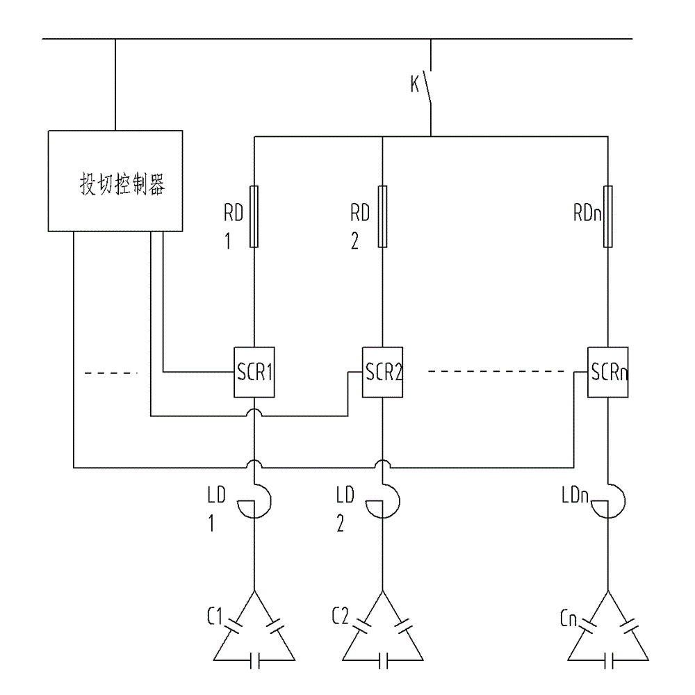
[0015] figure 1 The schematic diagram of the compensation circuit principle of the capacitor bank switching device of the present invention is shown. It can be seen from the figure that the compensation circuit is composed of n compensation branches, n=1, 2, 3, 4...natural integers, and each compensation branch is composed of The fuse RD, thyristor switch SCR, current limiting reactor LD and compensation capacitor C are connected in series, the input end of the switching controller is connected to the external bus, and the output end of the switching controller is connected to the control of the thyristor switch SCR At the end, the outer busbar is connected to the inner busbar connecting all compensation branches through switch K.

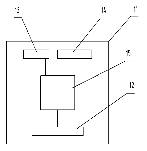
[0016] Figure 4 and Figure 5 The capacitor bank switching device shown includes a cabinet body 1, and the interior of the c...


PUM


Abstract

The invention discloses a compensating capacitor bank switching method and a compensating capacitor bank switching device adopting the method. The method mainly includes: working out a random function program with output values serving as sequence numbers of compensating capacitor banks, and selecting compensating capacitor banks switched into a power grid and compensating capacitor banks switched out of the power grid according to the random function output values. The compensating capacitor bank switching device comprises a plurality of capacitor banks (6), a capacitor bank switching controller (8), capacitor bank switching control switches (5) and a power factor meter (7), and a microprocessor (15) of the capacitor bank switching controller (8) is connected with a signal output end of the power factor meter (7) through an input interface circuit (13) and is connected with a control signal end of each capacitor bank switching control switch (5) through an output interface circuit (14). Compared with the prior art, the compensating capacitor bank switching method and the compensating capacitor bank switching device are capable of effectively solving the problem of poor operating reliability of a reactive power compensation device.

Description

technical field [0001] The invention relates to the technical field of electric equipment production and manufacturing, in particular to a method and equipment for switching on and off a capacitor bank to a grid for reactive power compensation. Background technique [0002] At present, the reactive power compensation device widely used in the power system is generally composed of a cabinet and an instrument installed in the cabinet, a capacitor bank switching controller, each capacitor bank switching control switch, and multiple capacitor banks. "A new type of low-voltage power capacitor bank multi-group hierarchical cycle automatic switching control device" (patent application number is 02100214.2, patent publication date is July 30, 2003) and "Dynamic capacitor switching device and its switching Cutting method" (Patent No. 01114333.9, authorized announcement date is August 18, 2004). The switching control of the capacitor bank generally adopts the control method of seque...

Claims


Application Information

Patent Timeline
Patent Type & Authority Patents(China)
IPC IPC(8): H02J3/18
CPCY02E40/30
Inventor 叶金叶光岩
Owner LIUZHOU HAIGE ELECTRICAL
Why Eureka
Try Eureka